





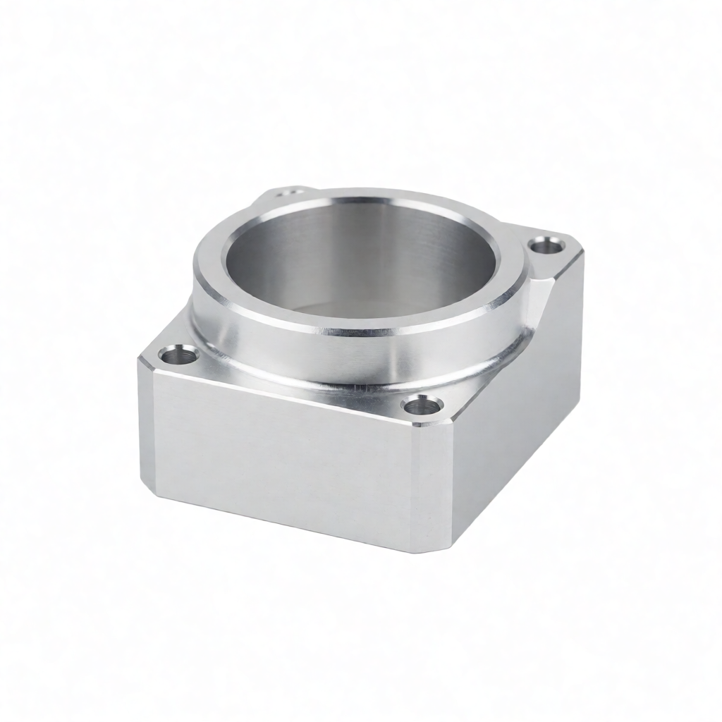
In CNC part design, the meshing of complex curved surfaces and the support strategy directly determine the executability of the machining program and the consistency of the finished product. For irregular structures involving five-axis linkage processing, if the initial CAD model or STL mesh accuracy is insufficient, it is very likely to cause tool path skipping, overcutting or residual material, ultimately affecting the surface finish and assembly accuracy. Before importing the design, engineers need to clarify the mesh resolution (usually 0.1mm-0.5mm, depending on the rate of curvature change) and support logic to ensure that the CAM software can accurately identify features and generate collision-free cutting trajectories. ShowyMetal offers full-process support from DFM review to 3/4/5-axis milling. For such complex geometries, we achieve stable delivery with a dimensional tolerance of ±0.01mm and a surface roughness of Ra0.4μm by optimizing model simplification and process path planning, helping R&D and procurement teams shorten the verification cycle.
Key Points of DFM Review before Complex Surface Design
Before initiating CNC machining, the DFM (Design for Manufacturing) review in the design stage is the key to avoiding rework later on. Many engineers are accustomed to directly exporting high-precision STL or STEP files, but they overlook the process feasibility of geometric features. For instance, when using a standard ball knife, it is difficult to clean the root of a rounded corner with an indented R0.5mm or less, and it is easy to leave a "knife puncture" mark. Blind holes with a depth-to-width ratio exceeding 5:1 pose risks of tool breakage and chip removal. It is recommended to introduce process constraints at the CAD stage: ensure that the minimum concave radius is greater than the tool radius, avoid completely enclosed deep cavities, or reserve process holes. After receiving the drawings, ShowyMetal's engineering team will first conduct a model check to identify potential interference points and unmachinable areas, and provide modification suggestions to ensure that the design meets the equipment capability boundaries for 3/4/5-axis processing.
- Minimum feature size: It is recommended that the concave R be ≥ 0.5mm (corresponding to the D1mm ball knife), and the convex R can be appropriately relaxed according to the clamping direction.
- Depth limit: It is recommended that the depth-to-diameter ratio of deep blind holes be ≤ 5:1. If the ratio exceeds this, deep hole drills should be used and chip removal solutions should be considered.
- Clamping clearance: A safety gap of 1-2mm should be reserved in the coverage area of the fixture to prevent collision during processing.
Precision Selection and Optimization Strategies for Grid Division
For complex surfaces, CAM software typically performs tool path calculations based on triangular meshes (STL) or NURBS surfaces. Mesh Resolution is the core parameter for balancing calculation time and processing accuracy. If the grid is too large (such as 1mm), a step effect will be formed in areas with drastic curvature changes, causing the actual tool path to deviate from the theoretical surface, resulting in overcutting or material retention. If the grid is too small (such as 0.01mm), the file size will increase sharply, the simulation time will be long, and it is easy to cause tool path jitter due to numerical noise.
It is recommended to adopt Adaptive grid Strategy: Use a thicker grid (0.5-1.0mm) in flat areas, and denser it to 0.1-0.2mm in areas with a curvature radius less than 5mm. Experience shows that for complex aluminum alloy structural components, a 0.2mm grid step size can ensure the surface quality (residual height <0.05mm) while keeping the CAM calculation time within a reasonable range. In addition, it is crucial to check the consistency of the normal direction of the grid. An inverted normal can cause the CAM software to misidentify the material side and the air side, leading to a catastrophic collision.
The differences in application scenarios between STEP and STL
The STEP format retains the NURBS surface definition and is suitable for models after regular surfaces and Boolean operations. CAM software can directly read the geometric definition to generate tool paths, achieving the highest accuracy. The STL format is a collection of triangular patches, suitable for complex scanning data or non-standard surfaces, but it needs to undergo "denoising" and "simplification" processing. For models with a large number of small holes or thin ribs, it is recommended to retain the STEP file as the benchmark and only use STL for collision checking in the CAM simulation stage to balance efficiency and accuracy.
The influence of Support Structure Design on Processing stability
Unlike traditional 3D printing, the "support" in CNC machining mainly refers to process support, positioning reference and weight reduction structure. For thin-walled or complex curved surface parts with long cantilevers, insufficient rigidity can cause cutting vibration and affect the surface finish. During the design stage, process protrusions (Dog-bone) or local thickened areas should be added for clamping and positioning. For instance, when machining a shell with a 45° bevel on a 5-axis machining center, if the bevel length exceeds 20mm and the wall thickness is only 2mm, it is recommended to add a 5mm wide process bridge on the inner side. After the machining is completed, it can be removed by drilling or milling.
In addition, the flatness of the support surface directly affects the repeat positioning accuracy. It is recommended to specify the reference plane A as the clamping surface, and its flatness tolerance should be controlled within 0.02mm. If a part has multiple free surfaces, it is necessary to clearly define the primary and secondary datum to avoid stress deformation caused by simultaneous clamping of multiple datum. For large curved surface parts, a split processing strategy can be adopted. First, process the main reference surface, and then flip and clamp to process other surfaces. The centering can be improved through pre-drilling positioning.
Comparison of Meshes with different topological Structures and process schemes
For several common complex surface topological structures faced by engineers, there are significant differences in the focus of mesh division and the selection of processing techniques. The following table compares the differences in mesh accuracy, tool selection and support strategies among three typical structures: "regular freeform surfaces", "deep cavity polyhedrons" and "thin-walled irregular parts", for reference in design and selection.
| Structural type | Recommended mesh accuracy | Main tool selection | Support/Clamping strategy | Common failure modes |
|---|---|---|---|---|
| Regular freeform surface (Such as the casing, impeller) | 0.2-0.5 mm (curvature.
« Previous
cnc part design: Chip removal and cooling channels for deep hole machining
Next »
cnc part design tolerance allocation: Selection of key dimensions and fit dimensions
Recommended Reading
Related ContentExplore more articles that may interest you.
Quote in 2 Hours
Send Your Drawing, Get a Quote in 2 Hours.Send your STEP / DWG / PDF drawing and our engineers reply within 2 hours with a detailed quote including free DFM analysis and process recommendations — no obligation. Send Us Your Drawing — We Handle the RestSend your STEP / DWG / PDF drawing and get a detailed quote with free DFM analysis and process recommendations within 2 hours. No minimum order — from 1 piece.
Live inquiries
|



