






The core of CNC machining of aluminum alloys is to avoid structures that cause cutting tool breakage, workpiece deformation or tolerance instability during the design phase. For technical procurement and engineers, understanding "design for manufacturability"(DFM) can save weeks of rework cycles than simply focusing on material grades. Common aluminum materials such as 6061-T6, 7075-T6 or 5052 have excellent cutting performance, but if there are deep grooves, thin walls or complex internal angles in the structure, it is easy to cause vibration marks, stress release deformation and even tool fracture in mass production. This article will analyze five types of high-risk structures in depth and provide specific size limits, alternatives and acceptance criteria to help you identify risks before drawing issuance and ensure that the tolerance requirement of ±0.01mm is stably achieved.
Deep cavity and groove structure: invisible trap of tool diameter and aspect ratio
In aluminum alloy milling, Deep pocket and deep slot are the high incidence areas of tool chatter. The overhang length of the tool is limited by rigidity. When the ratio of groove depth to tool diameter (L/D) exceeds a certain threshold, the deflection of the tool in the cutting depth direction will increase sharply, resulting in surface roughness deterioration to Ra 3.2μm or more, and even tool collapse. Usually, it is recommended to control L/D within 3:1. If L/D reaches 5:1 or more, cutting parameters must be adjusted or process paths must be changed.
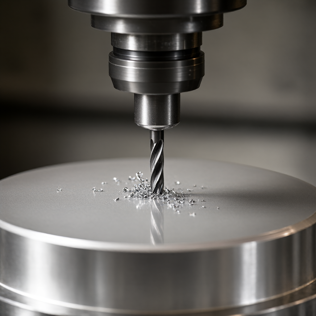
Structural Parameter Limitations and Alternatives
- aspect ratio limitation: Standard end mill machining deep groove, L/D recommendation ≤3. If deeper, should use rough machining allowance (0.5-1.0mm), change to a short knife for finishing.
- slot width limitThe groove width should not be less than 1.2 times the diameter of the tool, otherwise the tool cannot be stably centered and is prone to lateral offset.
- alternative solution: For blind holes or cavities that are too deep, consider turning (if rotational symmetry is present) or EDM to machine the sidewalls and CNC finish the bottom.
| L/D ratio | main risk | Suggested countermeasures |
|---|---|---|
| ≤ 3 | Conventional cutting, low risk | Standard high speed milling, using 4-or 5-edge end mills, moderate feed |
| 3 - 5 | Ripple appears, finish drops | Roughing and finishing, leaving a margin of 0.1-0.2mm for finishing, reducing the speed |
| > 5 | Very high risk of tool fracture, poor hole wall ovality | Use drill tap combination or EDM instead CNC only trim profile |
Thin-walled structures: stress relief and control of the "ear effect"
There is residual stress in aluminum alloy. When the wall thickness is too thin (usually less than 2mm), the material unloading during CNC cutting will cause elastic deformation of the workpiece, resulting in the so-called "Earping effect". This phenomenon is especially obvious in thin plate tensile parts or thin-walled shells, manifested as edge warpage and flatness. For mass production, if the clamping deformation is not considered during design, the subsequent correction process will greatly increase the cost.
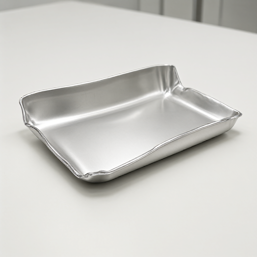
Thickness tolerance and clamping strategy
- minimum wall thickness3 axis milling recommended minimum wall thickness ≥2mm; if the wall thickness is between 1-2mm, vacuum suction clamping or custom flexible liner must be used to avoid point contact deformation.
- deformation reservation: Design drawings should reserve 0.05-0.10mm deformation allowance in thin-walled areas, or enable the "compensated thin-walled cutting" strategy in CAM programming (reduce the side cut to less than 0.05mm).
- stock option6061-T6 has better creep resistance than A380, suitable for thin-walled structures with high flatness requirements.
Acute and Internal R Values: Physical Constraints on Tool Geometry Limits
"No inner R" is a big design error in CNC machining of aluminum alloy. The tip radius of end mill physically determines the minimum size of internal fillet. If the design drawing contains right angle internal angle (R0), there must be a fillet with the size of tip radius after machining (for example, using 6mm tool, actual inner R≈3mm, need to deduct tool radius offset). Forcing to remove excess material through multiple passes is not only inefficient, but also easy to lead to stress concentration, which becomes the source of fatigue fracture.
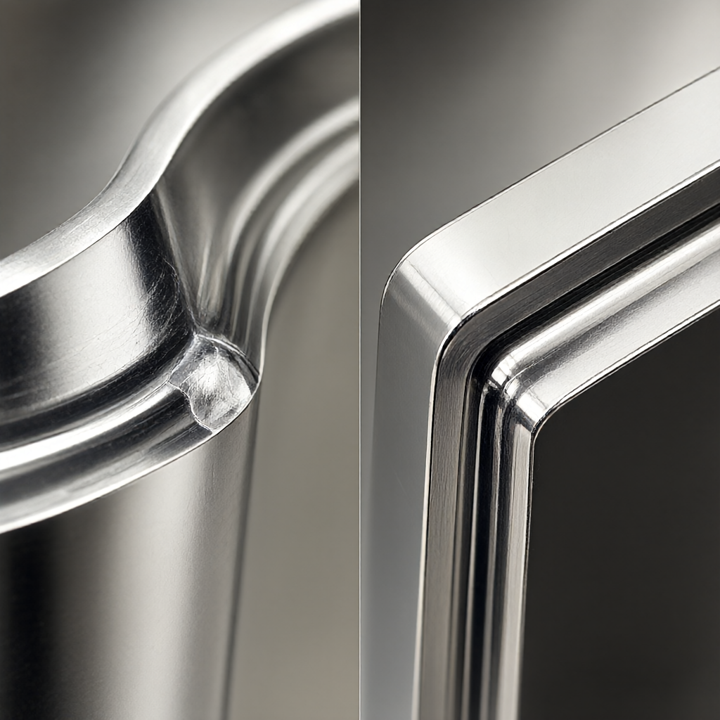
Internal R value setting specification
- minimum inner R: It is recommended that the inner R ≥ 1.5 times the tool radius. If a 1mm flat bottom cutter is used, the inner R is designed to be at least 0.5 mm, but the expansion space after tool wear should be considered.
- external R valueThe outer R is recommended to be ≥2mm, and too small an outer R will lead to a sudden load change at the corner of the tool and accelerate tool wear.
- alternative processIf the structure requires a minimum R value (e.g. 5)
Low (frequent tool change required) Medium (inclined feed) Tool breakage, chatter Split into multi-layer processing, or switch to EDM Thin-walled « Previous Deformation Control Technique of Thin Wall Parts in Aluminum Alloy Machining Next » Aluminum CNC machining selection guide: from material grade to tolerance standardRecommended ReadingRelated Content
Explore more articles that may interest you.
Quote in 2 HoursSend Your Drawing, Get a Quote in 2 Hours.
Send your STEP / DWG / PDF drawing and our engineers reply within 2 hours with a detailed quote including free DFM analysis and process recommendations — no obligation.
Send Us Your Drawing — We Handle the Rest
Send your STEP / DWG / PDF drawing and get a detailed quote with free DFM analysis and process recommendations within 2 hours. No minimum order — from 1 piece.
Live inquiries


