






Aluminum alloy thin-walled parts are easy to deform due to cutting heat, clamping stress and elastic recovery of materials in CNC machining, which leads to size out of tolerance or flatness failure. Accurate control of aluminum alloy thin-walled parts deformation requires collaborative optimization from four dimensions: process planning, tool selection, cutting parameters and clamping methods. For precision parts with wall thickness less than 2mm, it is recommended to adopt a "segmented cutting + rapid tool withdrawal" strategy and control the cutting force within the maximum radial force of 30N of the single tool to minimize the warpage risk caused by residual stress release. If your project involves thin-walled shells or large frame structures, refer to the DFM analysis report provided by our process engineering team to ensure production consistency.
Core Mechanism and Failure Mode of Deformation of Aluminum Alloy Thin-walled Parts
Aluminum alloys (e.g. 6061-T6, 7075-T6) have high specific strength and elastic modulus, but in thin-walled structures (wall thickness is usually defined as less than 2mm), their stiffness is extremely sensitive to small displacements. Deformation mainly results from three mechanisms:
- Thermal Effects of Cutting:Although the thermal conductivity of aluminum alloy is high (about 200-230 W/m·K), the local temperature rise caused by high-speed milling will still lead to microscopic thermal stress gradient, and the bending to the cutting direction will occur after cooling.
- Residual stress relief:Initial residual stresses exist in castings or extrusions. With material removal, the stress field redistributes, resulting in macroscopic deformation.
- Clamping deformation:Thin-walled parts have low bending rigidity, rigid clamping will lead to elastic deformation, springback after loosening, resulting in uneven machining allowance.
Failure characteristics often manifest themselves as out-of-planarity (>0.05mm/100mm) or critical mating surface size drift after machining. In aerospace and semiconductor vehicle scenarios, this deformation leads directly to assembly interference or hermeticity failure.
Process Path Planning: Layered Cutting and Margin Control
The traditional "one size fits all" strategy will inevitably lead to deformation on thin-walled parts, and the effective process path should follow the principle of "from coarse to fine, small steps and fast speed".
Strategy of reserving rough machining allowance
For 6061 aluminum parts with wall thickness of 1.5mm, it is recommended to keep a uniform allowance of 0.3-0.5mm after rough machining. Too large a allowance will lead to large cutting depth and uneven stress during finish machining; too small a allowance will not compensate for the deformation of the previous process. Interference inspection is carried out by CAM software to ensure that the allowance is distributed symmetrically.
Semi-finishing and thermal equilibrium
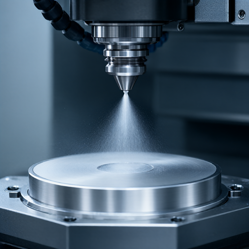
In the semi-finishing stage, high speed (8000-12000 rpm), small feed (0.05-0.1 mm/rev) strategy is used to reduce the unit cutting force. At this time, micro-lubrication (MQL) or high-pressure water cooling should be enabled to control the workpiece temperature rise within 10°C to reduce thermal deformation.
Finish withdrawal path
Finish milling is used, and the tool path spacing is controlled at 0.5-1mm to ensure the overlap rate. The key feature is that the cutting speed of the last 10% is reduced by 20%, and the use of fast tool withdrawal mode (G0 or G38 command) avoids the tool staying at the bottom of the groove.
Tool selection and parameter matching: reducing cutting impact
Tool geometry directly determines the smoothness of cutting. Thin wall machining disable round nose R or sharp corner tools, preferably large helix angle end mills.
| parameter items | Recommended values/characteristics | Engineering rationale |
|---|---|---|
| tool helix angle | 40°-55° (4 blades and above) | Large helix angles provide a "shear" effect, reducing axial forces and flutter risk |
| coating material of | TiAlN or uncoated high speed steel (HSS) | Aluminum easy to stick knife, hard coating friction coefficient needs to be low;HSS toughness is good, anti-chipping |
| Feed per blade (fz) | 0.08-0.12 mm/rev | Too small is easy to produce chip build-up, too large is the increase in cutting depth leading to deformation |
| Speed (S) | 10,000-15,000 rpm | High speed compensates for small cutting depth and maintains high surface quality (Ra<0.8μm) |
Note: When using carbide tools, it is necessary to ensure the sharpness of the cutting edge. Blunt tools will increase the extrusion area and greatly aggravate the deformation of thin-walled parts. Regularly monitor the wear of tools, and replace them if the VB value exceeds 0.1mm.
Clamping and support techniques: Minimizing constraint deformation
Clamping is the largest external variable of deformation. Too much rigidity is taboo, moderate flexibility is the key.
Vacuum adsorption and flexible fixture
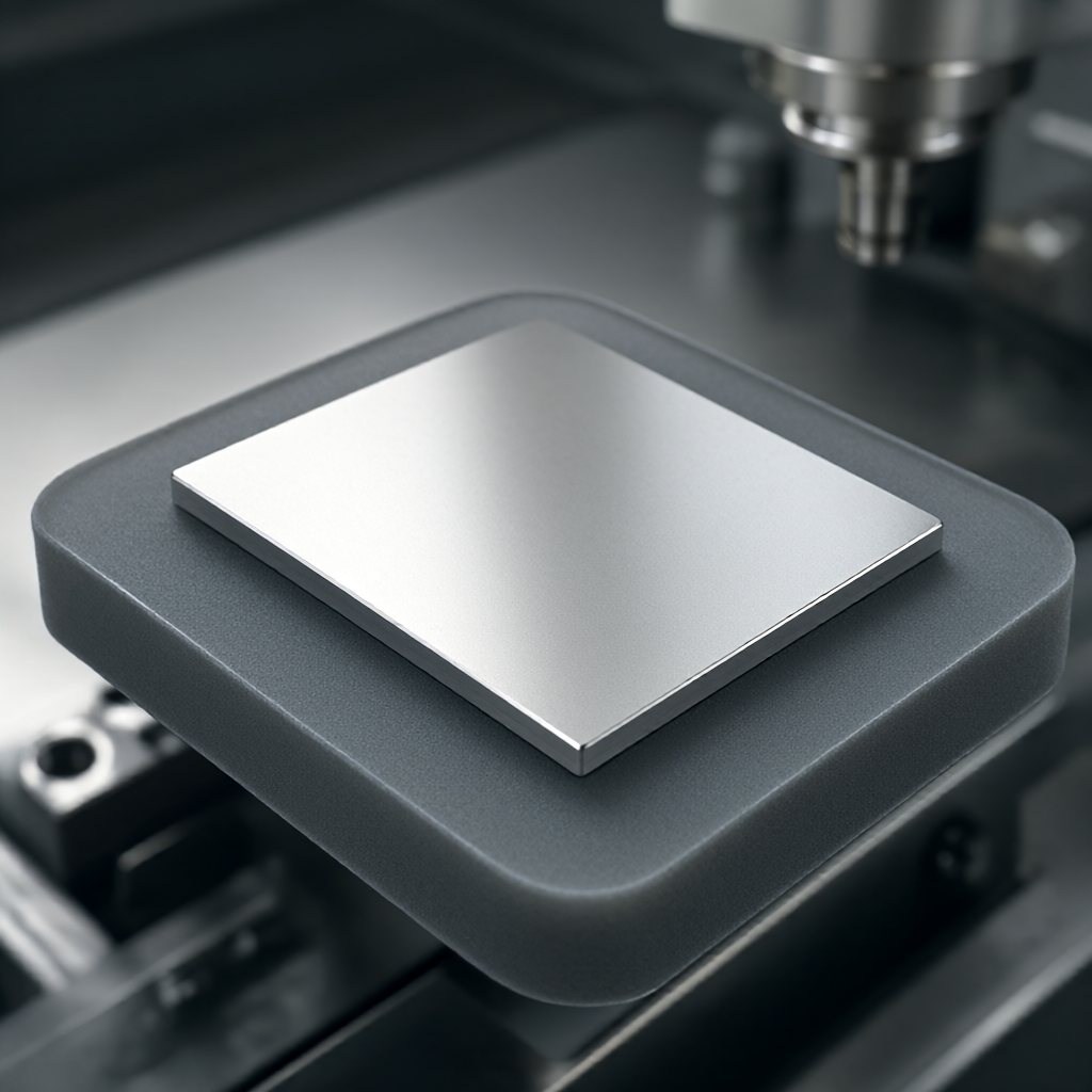
For flat sheets, vacuum suction platforms are recommended. With sponge or polyurethane membranes, uniform support is provided to avoid point contact indentations. For profiled parts, polyurethane (hardness Shore A 40-60) soft lining is designed, thickness 2-3mm, to absorb clamping forces.
Process holes and auxiliary supports
In long-sided thin-walled structures (such as radiator frames), reserve positioning process holes. Apply a small pre-tightening force (<10N),加工中保持支撑点连续。避免将支撑点放在薄壁悬臂端,支撑点应靠近刚性基体。
Split processing strategy
For complex shells, it is recommended to split the parts into two halves and process them separately, and finally assemble them by gluing or riveting. This method completely avoids the huge deformation risk of the overall processing, but increases the assembly process and requires a trade-off of efficiency.
Closed loop quality inspection and distortion correction
Deformation control is not a one-time action, but an iterative process.
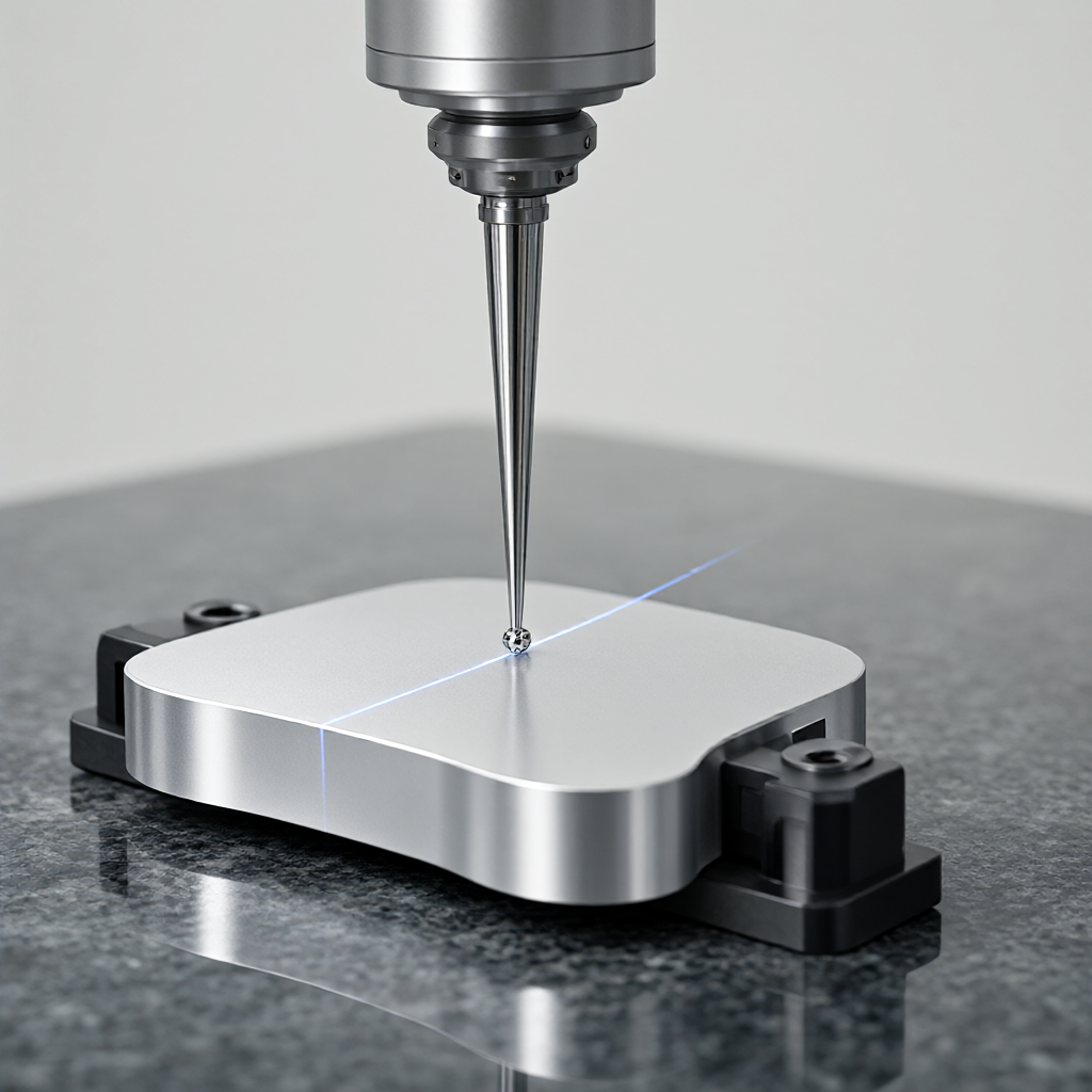
- Coordinate Measurement (CMM):Spot check 1 piece per shift, focusing on flatness and key hole location. Data feedback to CAM program, modify the tool path compensation value of the next piece.
- Optical autocollimator:It is used to monitor spindle perpendicularity and workpiece thermal drift with an accuracy of 0.5μm.
- Shape Memory Alloy Pin:In advanced applications, intelligent pins are used to monitor stress and trigger machine alarms in real time.
If a systematic bend of 0.02 mm in the direction of the cutter is detected, a depth of cut compensation of 0.02 mm should be added to this area in CAM. This "pre-deformation" correction method can significantly reduce the rejection rate in mass production.
Troubleshooting of common problems in processing aluminum alloy thin-walled parts
Why do aluminum alloy thin-walled parts warp after machining?
The main causes are uneven release of residual stress and accumulation of cutting heat. Check whether layered cutting is used and whether cooling is sufficient. If the warp direction is fixed, add reverse compensation allowance to the finishing path.
Thin-walled parts clamping easy deformation how to do?
Use low hardness polyurethane soft clamps or vacuum suction instead. Avoid direct clamping with rigid vice. Flexible bushings must be added and contact surfaces dispersed to reduce unit pressure below the yield limit of aluminum.
How to choose the right cutting fluid for machining aluminum thin wall?
Aluminum alloy thin-walled parts processing recommended use of synthetic water-soluble cutting fluid, concentration 8-12%. Synthetic fluid lubrication is good, and not easy to react with aluminum to form copper mud clogging microchannels. Avoid the use of high concentrations of sulfide oil, to prevent aluminum surface corrosion.
What tolerances can aluminum parts with a wall thickness of 1mm achieve?
Under strict process control (pre-deformation compensation + flexible clamping + high-speed milling), the size tolerance can be stabilized at ±0.02mm, and the flatness is 0.05mm/100mm. If pre-deformation correction is not done, it can only ensure ±0.05mm.
How to ensure the consistency of thin-walled parts in batch production?
The key lies in process standardization and on-line monitoring. Fixed tool compensation strategy, CMM full size inspection every 50 pieces, and record deformation trend line. Once the trend deviation, immediately suspend production, recalibrate the clamping reference.
Conclusions and recommendations for cooperation
ShowyMetal has 72 precision CNC machines and a complete inspection system, providing one-stop solutions from DFM analysis to batch delivery for all kinds of complex thin-walled structures. If you are faced with thin-walled deformation problems, welcome to provide drawings and technical specifications, we will develop a unique process optimization program for you.


