





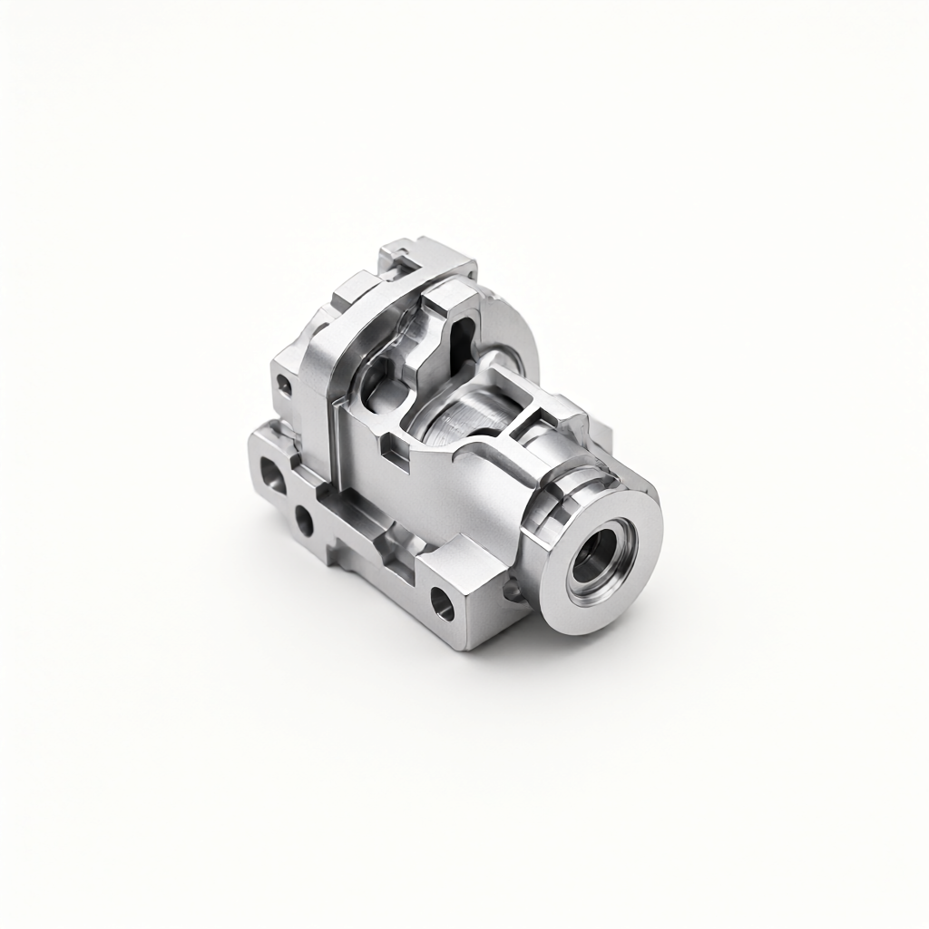
The Core Logic and Engineering Practice of Tolerance Allocation in CNC Parts Design
In the design of precision CNC parts, Tolerance distribution It not only concerns whether the parts can be assembled, but also directly determines the consistency of mass production, the quality of surface appearance and the ultimate cost competitiveness. Many engineers only focus on "whether it can be installed" during the drawing stage, while neglecting "whether it can be installed stably" and "whether there will be a failure in batch production". For high-end parts that adopt 3/4/5-axis milling or turning and milling compound processes, a reasonable tolerance system is the key to avoiding later rework and reducing the scrap rate. This article, from the perspective of engineering practice, analyzes the selection strategies for key dimensions and mating dimensions. Combining ShowyMetal's manufacturing capabilities (with an accuracy of ±0.01mm and a surface finish of Ra0.4μm), it explores how to achieve a balance between appearance quality and mass production efficiency while ensuring functionality through optimizing tolerance strategies. For projects that pursue high smoothness and flawless surfaces, the tolerance strategy needs to particularly take into account the influence of material deformation and heat treatment stress release.
The identification principles of key dimensions and mating dimensions
Not all dimensions require high-precision tolerances. Blindly setting the tolerance of the entire drawing to ±0.01mm will lead to an exponential increase in processing costs and may not necessarily improve product performance. During the design stage, it is necessary to clarify what constitutes Key dimensions (Key Dimensions).
- Matching dimensions It refers to the dimensions at which two or more parts come into contact and undergo relative motion or positioning. This is of Paramount importance in tolerance allocation. It is necessary to clarify whether it is clearance fit, interference fit or transition fit, and select the specific tolerance grade (such as H7/g6, H7/p6, etc.) by referring to ISO 286 or GB/T 1800 standards.
- Functional dimensions Dimensions that determine the movement trajectory, sealing effect or electrical performance of parts. For instance, the inner diameter of the hydraulic cylinder affects the sealing performance of the piston, and its tolerance must be strictly controlled.
- "Appearance dimensions The size that directly affects users' perception. For consumer electronics or high-end medical devices, although the appearance surface may not necessarily be involved in precise coordination, its flatness and contour need to be controlled to avoid visual errors.
For non-critical dimensions (such as chamfers and unimportant holes), it is recommended to relax to ±0.05mm or even ±0.1mm to free up manufacturing resources. This differentiated allocation strategy enables manufacturers to focus expensive precision equipment, such as 5-axis machining centers, on key processes.
The correspondence between standard tolerance grades and manufacturing costs
When choosing the tolerance grade, economy must be taken into consideration. Overly strict tolerances mean longer processing times, more frequent inspections and higher tool wear. The following is a comparison of the cost and difficulty of commonly used fit tolerance grades in CNC machining:
| Tolerance grade | Typical IT-level | Processing difficulty | Cost coefficient (relative) | Applicable scenarios |
|---|---|---|---|---|
| Ultra-precision | IT1-IT2 | Extremely high | 10.0 & | Precision instruments, optical components |
| Precision | IT5-IT6 | "High | 3.0-5.0 | High-speed spindles, precision bearings, semiconductor cavities |
| "Ordinary" | IT7-IT8 | "Medium" | 1.0-2.0 | General mechanical transmission, connecting parts |
| Rough | IT9-IT12 | Low | 1.0 & | Shell, non-load-bearing bracket |
Practical suggestions For most industrial applications, IT7 to IT8 is a relatively cost-effective range. If the mating surface requires extremely high smoothness (such as Ra0.4μm mirror effect), even if the tolerance is only IT7, sufficient deburring and polishing allowance should be reserved. In mass production, ShowyMetal can achieve stable appearance quality at IT6 level by optimizing the tool path strategy of the CNC program, avoiding sacrificing dimensional stability for aesthetic reasons.
Application of form and position tolerance (GD&T) in critical parts
Merely controlling dimensional tolerances is often insufficient to ensure assembly quality, especially for polyhedral parts machined on multiple axes. Shape and position tolerance Geometric tolerance can define the ideal shape of a part more accurately. In CNC design, the following points need to be particularly noted:
- Coaxiality For turning and milling compound machined parts, the coaxiality of the reference surfaces at both ends directly affects the rotational stability after assembly. If the coaxiality is not marked, the maximum solid boundary caused by the dimensional tolerance is followed by default, which may lead to actual assembly interference.
- Flatness For thin sheet parts or heat dissipation surfaces, flatness deviation can lead to uneven assembly clearance. It is recommended that the flatness be controlled within the range of 0.02 to 0.05mm to ensure that the contact surfaces fit closely.
- Positional degree For perforated plates or locating pin holes, positional accuracy can better ensure the relative positional relationship between holes than the dimensional tolerance of individual holes, avoiding assembly failure caused by "qualified dimensions but hole spacing deviation".
When drawing the blueprint, the Datum system should be clearly defined. Usually, the positioning surface is selected as the reference A, and the main mating hole/shaft is chosen as the reference B. Clear benchmark marking enables CNC programmers to quickly formulate clamping plans and reduce trial-and-error costs.
The influence of material properties on tolerance design
The cutting performance and coefficient of thermal expansion of different materials vary greatly, which directly affects the design strategy of tolerances.
Metal materials: aluminum, stainless steel and titanium alloy.
Aluminum alloys (such as 6061-T6, 7075) are easy to process, but their surface hardness is relatively low and they are prone to plastic deformation. For aluminum alloy appearance parts, it is recommended to reserve a machining allowance of 0.05-0.1mm in the tolerance for sandblasting or anodizing. The thickness of the anodic oxide film is usually 10 to 15μm, which slightly increases the surface size. Therefore, the inner hole mating surface needs to reserve space for the oxide film; otherwise, it may lead to an interference fit during assembly.
Stainless steel (such as 304, 316L) has a strong tendency to work harden and generates high cutting heat. If the tolerance is too strict, the tool wears out quickly and the size is prone to drift. It is recommended that low-temperature cutting fluid be used for stainless steel precision parts and the depth of each cut be controlled. For titanium alloys, due to their low thermal conductivity, they are highly prone to residual stress caused by local overheating, which in turn leads to part deformation. When designing precision structural components of titanium alloys, a deformation allowance after stress release should be reserved in the tolerance, or a process strategy of "reserving 0.1mm for precision turning/precision milling" should be adopted.
Engineering plastics: Considerations of Shrinkage Rate
Although ShowyMetal offers injection molding services, when CNC processing plastics such as nylon (PA66) and PEEK, attention should be paid to the material's hygroscopicity and shrinkage rate. The tolerance design of plastic parts is usually looser than that of metal parts, but if precise guidance is involved, thermal expansion at working temperatures needs to be taken into account. It is recommended to provide the material grade during the design stage so that the manufacturer can adjust the mold or CNC path according to the shrinkage rate.
Consistency Control and DFM Optimization in Mass Production
For mass production, having a single piece qualified is not enough. strong> Batch consistency It is the core pain point. When designing tolerances, the sources of variation in CNC machining need to be taken into account: tool wear, thermal expansion of fixtures, batch differences of materials, etc.
- Tolerance zone distribution If the average dimensional stability is required, it is recommended to adopt symmetrical tolerance. If it leans to one side (for example, the inner hole is usually distributed in the direction of small deviation and the outer axis in the direction of large deviation), the single-side deviation should be marked on the drawing, such as 25.000⁺⁰· ⁵⁰ ₀mm, rather than the asymmetrical 25.00±0.05mm. This helps to reduce the size fluctuation range between batches.
- DFM suggestions During the design review stage, the manufacturer will put forward DFM (Design for Manufacturability) suggestions. For instance, blind holes with too little depth can be changed to through holes to facilitate chip removal and tool entry, thereby making it easier to ensure the positional accuracy of the holes. Change the sharp corners to rounded corners to avoid stress concentration and tool chipping.
ShowyMetal is equipped with 72 CNC machines, including 3/4/5-axis machining centers, CNC lathes, and through-feed lathes, etc. During the batch production stage, we implement the "First piece confirmation" and "process inspection" systems, and use a three-coordinate measuring machine (CMM) for full-size inspection to ensure that the size distribution of each batch of parts meets the requirement of CPK≥1.33. This data-driven quality control ensures that even when the tolerance is set at ±0.01mm, stability can be maintained in mass production.
Matching of acceptance criteria and testing methods
The tolerance design must be matched with the detection means. If the drawing requires a hole diameter tolerance of ±0.005mm, but the customer specifies the use of ordinary calipers for acceptance, it is an invalid design. The common detection levels are as follows:
- "Ordinary grade" Calipers, micrometers. Suitable for tolerances above IT9, with rapid spot checks.
- Precision grade Pneumatic measuring instrument, high-precision micrometer. Suitable for IT7-IT8 tolerances, real-time online detection.
- Ultra-precision grade Coordinate measuring machine (CMM), optical image measuring instrument, roughness meter. It is applicable to IT6 and form and position tolerance inspection.
For the requirement of surface finish Ra0.4μm, it must be clearly stated in the drawing whether it is "all outer surfaces" or "key mating surfaces/appearance surfaces". Generally, the non-contact surface can be relaxed to Ra1.6 or Ra3.2 to reduce costs. If anodizing or electroplating is involved, the surface condition before and after surface treatment should be specified, as the electroplating layer will change in size (electroplating is bidirectional thickening, while anodizing mainly thickens).
Common Failure Modes and Avoidance Strategies
Based on engineering experience, the following three failure modes occur frequently in CNC parts:
- Assembly interference The reasons are usually that no surface treatment allowance is reserved or the tolerance fit is improperly selected. "Avoid" Communicate with the manufacturer about the surface treatment process in the early stage of design and calculate the final dimensions. For interference fit, reserve the estimated assembly force value.
- Appearance defects (scratches, vibration marks) The main reasons are unreasonable tool paths or overly fast feed rates. "Avoid" Specify the processing sequence of key appearance surfaces (such as final finishing milling); For surfaces sensitive to vibration marks, a strategy of small cutting depth and high rotational speed is required. ShowyMetal, through its high-gloss surface process, can effectively eliminate the tool marks left by conventional processing.
- Dimensional drift The main reasons are the release of residual stress in the material or inconsistent measurement benchmarks. "Avoid" For high-risk materials such as titanium alloys and spring steel, add aging treatment processes; Unify the measurement reference to avoid cumulative errors caused by multiple installations.
FAQ: Common Questions about Tolerance Design of CNC Parts
Why can't the tolerance of CNC machining be arbitrarily set at ±0.001mm?
Theoretically, modern CNC machines can achieve micron-level precision, but a tolerance of ±0.001mm (1 micron) requires extremely high environmental control (constant temperature and humidity) and expensive inspection equipment (such as laser interferometers, high-precision CMM). For the vast majority of industrial applications, ±0.01mm can already meet over 90% of the high-precision requirements, and the cost is controllable. Blindly pursuing overly strict tolerances can lead to an extension of the delivery period by 3 to 5 times and increase the risk of scrapping due to environmental fluctuations.
2. In the fit dimensions, how should the tolerance zones for the shaft and the hole be selected?
The selection should be based on the nature of the coordination. If free rotation and precise positioning are required, clearance fit (such as H7/f6) can be selected. If tight positioning is required and occasional disassembly is necessary, a transition fit (such as H7/k6) can be selected. If long-term connection is required and torque transmission is needed, an interference fit (such as H7/s6 or H7/u6) can be selected. When designing, the GB/T 1801 standard should be referred to, and a comprehensive judgment should be made in combination with the assembly process (whether cold mounting or hot mounting can be used). The technical team of ShowyMetal can provide simulation analysis to help optimize the selection.
What consequences can result from incorrect marking of form and position tolerances?
If the form and position tolerance markings are missing or the references are incorrect, CNC programming can only compensate for processing based on dimensional tolerances. This may result in the part dimensions being within the tolerance range, but the shape deviation exceeds expectations. For instance, if the positional degree of the holes is not marked, both holes may be qualified but the distance between them is too large, resulting in the inability to pass through the pins simultaneously during assembly. Correct GD&" The T marking can clearly define the independent control requirements for "shape" and "position", reducing the number of mold trials.
4. What impact does surface treatment have on the tolerance of CNC parts?
Electroplating is a bidirectional thickening process, with an increase of 10-25μm on each side. As a result, the inner hole becomes thinner and the outer shaft thicker. Anodic oxidation mainly thickens (10-15μm), and the inner hole becomes thinner. Sandblasting will slightly cut the surface (10-20μm). Therefore, when designing tolerances, surface treatment allowances must be reserved. For instance, if the final assembly clearance requirement is 0.05mm and the surface needs to be electroplated, the CNC machining size should be approximately 0.02 to 0.05mm smaller than the theoretical size. The specific value needs to be determined according to the process specification.
5. In mass production, how can we ensure the consistency of tolerances for each part?
The key lies in the monitoring of process capability (CPK). After the first piece is confirmed, the manufacturer needs to use statistical process control (SPC) to monitor the distribution of key dimensions. If CPK is lower than 1.33, the cutting parameters need to be adjusted or the tool replaced. Before mass shipment, ShowyMetal conducts 100% full-size inspection or random inspection in accordance with AQL standards, and provides a complete inspection report (including CMM data) to ensure batch consistency and the agreed appearance is free of scratches and defects.
Conclusions and Action Recommendations
Reasonable tolerance allocation is the prerequisite for precision manufacturing. Design engineers should achieve a balance between cost and quality on the basis of ensuring functionality by distinguishing critical dimensions from non-critical ones, rationally selecting tolerance grades, clearly defining form and position tolerances and reference systems, and closely collaborating with manufacturers for DFM optimization. For projects that pursue high appearance quality and strict dimensional accuracy, it is recommended to conduct professional evaluations in the manufacturing process as early as possible.
If you have complex CNC part design drawings in hand or need tolerance optimization and DFM review for specific materials such as titanium alloy and stainless steel, you are welcome to submit your drawings and technical specifications. Our engineering team will provide detailed feasibility analysis, tolerance suggestions and bulk quotations within 24 hours to help you efficiently implement high-consistency precision parts projects.



