





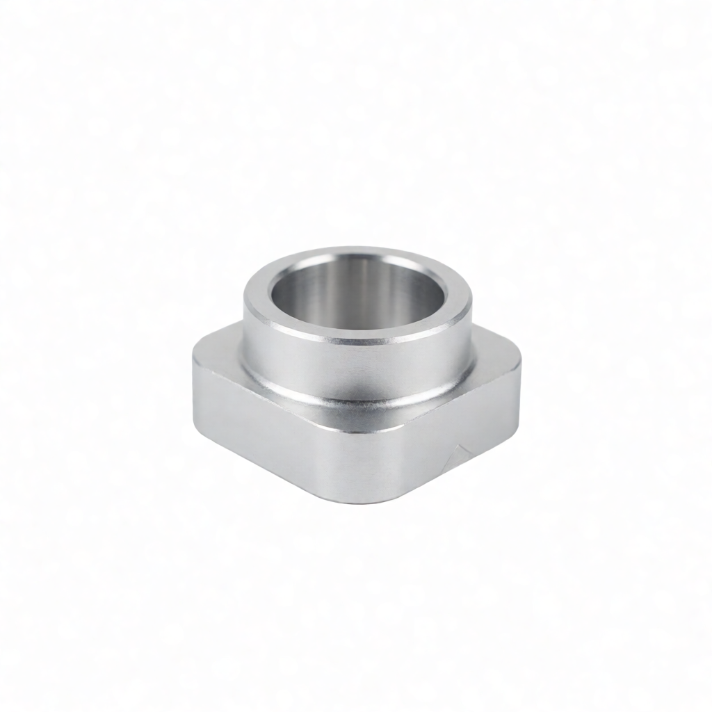
Chip removal and Cooling in Deep Hole Machining: Core Design Considerations
In the design of precision CNC parts, deep hole machining (usually referring to holes with a length-to-diameter ratio L/D ≥ 10:1) is an extremely challenging process. For engineers and purchasers, deep holes are not only geometric features but also a bottleneck for manufacturing stability. Common failure modes include chip blockage leading to tool breakage, poor heat dissipation causing hole diameter deviation, and deterioration of the surface roughness of the hole wall. When dealing with the customization of such precision CNC parts, ShowyMetal focuses on addressing two core pain points: chip removal and coolant penetration. By optimizing the internal cooling structure, rationally selecting cutting tools and setting up chip-breaking grooves, we can keep the scrap rate of deep hole processing at an extremely low level and ensure the consistency of batch production. For parts with deep hole structures, it is recommended to intervene in the assessment at the DFM stage to avoid potential risks in subsequent mass production.
The physical principles and main challenges of deep hole machining
Chip transfer mechanism and Clogging risk
In deep hole machining, chips need to be transferred to the outside of the hole within a narrow and long helical groove. If the chips are too long, they will wrap around the hole in a "brush" shape, increasing frictional heat and hindering the flow of coolant, which in turn leads to thermal deformation of the workpiece. When the L/D ratio exceeds 15:1, the conventional chip removal mode is highly likely to fail. At this point, the friction coefficient between the chip and the hole wall increases significantly, not only accelerating tool wear but also possibly scratching the machined surface, thus failing to meet the high finish requirement of Ra0.4μm.
Thermal balance and Tool Life
Due to chip retention, the cutting heat cannot be dissipated in time, and the local temperature rise can reach several hundred degrees Celsius. For highly difficult-to-cut materials such as stainless steel and titanium alloy, heat accumulation will rapidly reduce the hardness of the cutting tool. The detection data from ShowyMetal's three-coordinate measuring machine and roughness tester show that unoptimized deep hole machining often leads to positive deviation of the hole diameter (thermal expansion) and out-of-tolerance roundness. Therefore, establishing an effective cooling channel is a prerequisite for maintaining dimensional stability (±0.01mm tolerance).
Engineering Design Strategies for Chip removal and Cooling channels
Internal Cooling structure optimization
For solid drill bits or deep hole tool holders, internal cooling is the most effective means. When designing, it should be ensured that the diameter of the cooling hole is no less than 1/3 of the drill bit diameter, and the flow channel from the inlet to the shank is unobstructed. If the part is a solid shaft type, the position and Angle of the internal cold channel should be marked on the drawing. Generally, the opening Angle should be adjusted according to the feed rate to form a high-pressure jet in the chip area.
External cooling and nozzle layout
For cases where through holes or blind holes are relatively shallow, external high-pressure coolant can be used as a supplement. The nozzle should be aimed at the entrance of the cutting zone to avoid direct impact on the machined surface. On the turning and milling compound center, ShowyMetal often uses dynamic nozzles to follow the tool, ensuring a constant pressure inside the protective cover and removing most of the heat from the chips. Nozzle hole positions should be reserved in the design drawings. The hole diameter is generally recommended to be between 6 and 10mm, and the flow rate needs to reach 50 to 80 L/min to effectively penetrate the chip layer.
Tool selection and cutting parameter matching
The cutting tool is the end effector of the chip removal system. The selection of deep hole drills with large chip slots (such as BTA or PRD system tools) can significantly improve chip removal. The following is a comparison of the recommended geometric features and parameters of cutting tools under different materials:
| Material type | 推荐刀具类型 | 关键几何特征 | 推荐切削速度 (m/min) | 排屑方式 |
|---|---|---|---|---|
| 铝合金 (6061/7075) | 单刃深孔钻 | 大容屑槽,刃尖角 135° | 300 - 600 | 气液混合或高压内冷 |
| 不锈钢 (304/316) | 双刃/BTA 系统 | 强化涂层,宽刃,深槽 | 80 - 150 | 强制内冷,高压射流 |
| 钛合金 (TC4) | 微细切削深孔刀 | 小前角,大后角,锋利刃口 | 50 - 100 | 低温冷却,短切屑设计 |
| 工程塑料 (PEEK) | 硬质合金深孔刀 | 双刃自定心,无涂层 | 200 - 400 | 干切或微量润滑 |
注:切削速度需根据具体 L/D 比值下调。当 L20:1 时,建议速度降低 20%-30%,以牺牲效率换取稳定性。断屑槽的螺旋角需与进给率匹配,确保切屑呈 C 型或 6 型卷曲,便于排出。
实操要点:从 DFM 到量产的管控
DFM 审核重点
- 冷却孔位置:避免冷却孔正对零件受力面或外观面,否则易留下冷流痕。
- 深孔直径公差:深孔加工易产生锥度,公差建议放宽至 H7-H8,若需 H6 级精度,需增加精镗或铰孔工序。
- 盲孔底部清角:钻头无法加工直角底部,设计时需预留 90°-120° 的倒角空间,或注明使用平底钻头。
- 排屑空间:相邻孔间距需大于 1.5 倍孔径,防止排屑通道干涉。
制程监控手段
在 ShowyMetal 的 72 台 CNC 设备集群中,深孔工序通常安排在专用加工中心上进行。我们采用在线断屑监测技术,通过传感器监测振动频谱,一旦检测到切屑堆积引起的异常振动,立即停机清理。 出货前,使用三坐标测量机(CMM)抽检孔径、圆度及同轴度,确保符合 ISO 2768-mK 或更高标准。对于关键深孔,我们还执行内窥镜全检,确认孔壁无残留切屑及划伤。
常见失效模式与规避方案
孔壁划痕与拉毛
成因:切屑未被完全冲走,在孔壁滑动摩擦;或冷却不足导致工件热膨胀卡刀。
规避:提高冷却压力至 100-150 bar;采用带冷却内孔的刀具;降低进给率 10%-20%;在刀具刃口增加抛光处理。
刀具折断
成因:切屑缠绕导致扭矩激增;或排屑通道堵塞引起刀具过热退火。
规避:优化断屑槽参数;定期清理切屑收集器;监控主轴电流,设定过载保护阈值;对于超长深孔,分两次进刀并中间排屑。
FAQ:深孔加工设计常见问题
深孔加工的长径比(L/D)有没有较为限制?
没有较为限制,但成本与难度随 L/D 指数级上升。常规 3 轴/4 轴设备可处理 L/D ≤ 20:1 的深孔。若超过 30:1,建议采用专用深孔钻床(如 BTA 系统)或考虑将零件结构改为薄壁套式,由 ShowyMetal 提供车铣复合加工方案。
如何确定冷却液的压力和流量?
压力取决于切屑长度。短切屑(<5mm)需 50-80 bar 高压穿透;长切屑需 100+ bar。流量一般 30-60 L/min,需根据刀具内部流道截面积计算,确保雷诺数处于湍流状态以强化换热。建议在设计阶段与供应商共同模拟流道。
不锈钢深孔加工容易变形,如何预防?
不锈钢韧性大、导热差,极易热变形。预防关键在于“快”与“冷”:采用大切削深度、高切削速度以快速切出;使用低温乙二醇基切削液,并强化内冷。设计时避免长悬臂结构,增加工艺支撑。
盲孔深孔加工后,底部会有残留,需要特殊设计吗?
钻头是锥形刃口,盲孔底部必然有未加工锥面。若底部平整度要求高,需在图纸中明确注明“底部倒角”或“平底加工”,或预留余量由后续铣削工序完成。ShowyMetal 支持在单一工序中通过换刀完成深钻与底部铣平。
ShowyMetal 支持哪些材料的深孔定制加工?
我们支持铝、钢、不锈钢、黄铜及钛合金等金属,以及 PEEK、POM 等工程塑料的深孔加工。对于复杂形状的金属深孔,我们可利用 5 轴联动优势,优化刀具路径以避开干涉;对于塑料件,则采用微量润滑(MQL)技术,减少内应力变形。
结论与合作引导
深孔加工的设计核心在于“排屑顺畅”与“热控制”。通过将内部冷却结构纳入初始设计、匹配合适的刀具几何参数,并执行严格的制程监控,可以消除绝大多数批量生产风险。ShowyMetal 凭借 72 台 CNC 设备的规模优势及完善的质检体系(三坐标、光学测量、粗糙度仪),能够高效交付高一致性的深孔零件。 如果您手中有含深孔结构的图纸,建议尽早发起技术评审,我们将提供免费的 DFM 分析报告及快速报价,助您规避量产陷阱。



