





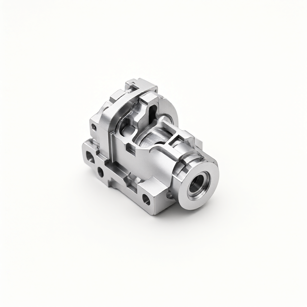
In the mass production of precision structural components, QC checkpoints for CNC machined aluminum parts with ±0.01mm tolerance are the core link for controlling yield rates. Aluminum alloys (such as 6061, 7075) are prone to elastic and thermal deformation during CNC milling and turning due to their high machinability and low thermal conductivity. Many engineers often misattribute this to tool wear, when in fact it is mostly caused by the release of clamping stress or improper program compensation. This article provides an in-depth analysis of how to establish a closed-loop quality control system—from process parameters to inspection methods—under the extreme ±0.01mm tolerance limit, ensuring consistency and stability in batch deliveries.
Why aluminum parts are highly susceptible to out-of-tolerance deviations at ±0.01mm
Although aluminum alloys are easy to machine, they exhibit complex physical properties in high-precision scenarios. First, aluminum has a high linear coefficient of thermal expansion (approximately 23-24 μm/m·K). If local temperature rises caused by cutting heat are not fully dissipated, they will cause slight elongation of the workpiece; subsequent cooling and rebound lead to dimensional deviations. Second, common grades like 6061 contain residual internal stresses. After the blank is cut or a large amount of material is removed in the initial rough machining, the release of stress causes "warping." If finishing is performed directly, the released stress will alter the part's geometry again after being set aside for several hours, resulting in out-of-tolerance readings during re-inspection.
In addition, insufficient machine tool rigidity or fixture clearances are potential risks. Within a ±0.01mm tolerance band, 0.005mm of fixture deformation or tool runout are directly translated into dimensional errors. Therefore, process control must be moved upstream, relying not just on final inspection, but on real-time monitoring of cutting status and workpiece condition during the machining process.
The impact of material selection and pre-treatment on precision
Grade comparison and stress control
Different aluminum materials have different sensitivities to precision. T6 temper is generally more stable than F temper (annealed) because it has undergone solid-solution treatment and artificial aging, resulting in a more uniform internal structure. For high-precision structural parts, it is recommended to use 6061-T65 (extruded bars/profiles) or 7075-T6 (plates), and to confirm that the supplier provides material that has undergone aging stabilization treatment. If the part has an asymmetric shape or uneven wall thickness, it is recommended to add a natural aging (holding for 48-72 hours) or artificial pre-heating (holding at 150-200°C for 2 hours) process before finishing to release residual stresses.
- 6061-T6: Good comprehensive performance, suitable for most structural parts, with moderate coolant consumption.
- 7075-T6: High strength, but with high cutting forces and a tendency to chip buildup, requiring sharper tools; suitable for high-strength critical components.
- 5052-H32: High corrosion resistance, but lower tensile strength; suitable for non-load-bearing aesthetic parts.
Cutting process parameters: balancing efficiency and precision
When pursuing ±0.01mm precision, the finishing strategy involves the counter-intuitive application of "small depth of cut, wide cut" or "large depth of cut, narrow cut." It is generally recommended to control the finishing allowance at 0.05-0.10mm to avoid the influence of tool path marks left by rough machining on surface finish and dimensional stability. Spindle speed must be calculated based on tool diameter to achieve peripheral speed; for 6061 aluminum, a peripheral speed of 150-300 m/min is usually recommended. Feed rate must consider smooth chip evacuation to avoid chips entangling and scratching the machined surface.
For tool selection, using a sharp rake angle (e.g., 15°-20°) reduces cutting forces and lowers workpiece deformation. Coated tools (such as TiAlN or AlCrN), while not strictly necessary for aluminum, improve resistance to tool adhesion and reduce surface pull marks. For complex curved surfaces, 5-axis simultaneous processing is recommended to maintain the tool axis at 90° to the machined surface or in an optimized posture, avoiding forced lateral forces caused by tool shank interference.
Fixture design and avoidance of elastic deformation
Fixtures are the invisible killers of precision. For thin-walled or slender aluminum parts, insufficient rigidity causes indentations at clamping points, which rebound into bumps after release. When designing fixtures, the "isothermal" principle must be followed; fixture materials (such as granite, cast iron, or aluminum alloy fixtures) must match the thermal expansion characteristics of the workpiece, or fixtures should be pre-heated to a uniform room temperature state before machining. For thin sheets, vacuum suction fixtures are a preferred solution to avoid local deformation; for deep-cavity parts, low-stress membrane fixtures (such as Duraline) can replace traditional V-blocks, distributing clamping force evenly across the entire contact surface to avoid point-load deformation.
The selection of datums is critical. Follow the "3-2-1" positioning principle to eliminate over-constraint. For multi-hole or multi-cavity parts, the effect of machining sequence on cumulative dimensional errors must be considered. For example, when machining hole system A first and then hole system B, the tolerance of B may be affected by the overall displacement of the workpiece after A is machined. In this case, it is recommended to add a "stress release" annealing step in intermediate operations or adjust the machining sequence to ensure that the critical surfaces for finishing are the last to release stress.
In-process online inspection techniques during CNC machining
Relying on offline sampling inspection is highly risky under a ±0.01mm tolerance; On-Machine Inspection (OMI) is recommended. Using probes from brands such as Renishaw allows for dynamic compensation of critical dimensions during the machining process.
- Tool wear monitoring: Measuring tool length and diameter changes with a probe to automatically modify G-code dimensional drift caused by tool wear. Compensation value (W compensation).
- Workpiece Clamping Verification
- Real-Time Confirmation of Critical Dimensions
Acceptance Criteria for Dimensional Tolerances and Surface Roughness
Dimensional accuracy typically follows ISO 2768 or GD&T standards. For critical fitting surfaces with a tolerance of ±0.01mm, the choice of inspection method directly affects the validity of the results. A standard vernier caliper has a resolution of 0.01mm and suffers from parallax error, making it insufficient for reliable inspection at this precision level. A micrometer (resolution 0.001mm) or a Coordinate Measuring Machine (CMM) must be used.
Surface roughness Ra values directly affect fitting clearances. Ra 0.4μm is a common target value for precision turned or milled aluminum parts. Optical interferometers or laser non-contact roughness meters are recommended for inspection to avoid measurement bias caused by stylus head indentation on soft aluminum surfaces (false precision). If the part surface requires anodizing, an oxide film allowance of 0.05-0.10mm must be retained before anodizing, as the oxide film will increase the surface dimension by 0.01-0.03mm.
| Inspection Tool | Resolution | Applicable Scenarios | Limitations |
|---|---|---|---|
| Vernier Caliper | 0.01mm | Rough inspection, non-critical dimensions | Cannot distinguish 0.005mm deviations; high parallax; not recommended for ±0.01mm critical surfaces |
| Electronic Micrometer | 0.001mm | Diameter, thickness, clearance | Requires regular calibration; probe indentation may affect aluminum surface |
| Coordinate Measuring Machine (CMM) | 0.0005mm | Complex curved surfaces, spatial coordinates, shape tolerances | High cost, low efficiency; requires constant temperature environment (20±2°C) |
| Image Measuring Instrument | 0.0002mm | Planar contours, hole center distances, 2D features | Limited to 2D planes; cannot measure inside deep cavities |
Analysis of Common Issues and Mitigation Strategies (FAQ)
Why do aluminum parts shrink in size after being left overnight post-machining?
This is typically the combined result of thermal expansion/contraction and residual stress release. If machining generates little chip heat removal or inefficient heat dissipation, the internal temperature of the workpiece remains higher than room temperature, causing contraction upon cooling. Additionally, if sufficient stress relief has not been performed, residual compressive stress causes inward deformation after external material removal. It is recommended to add an aging process before finishing and allow the part to rest at room temperature for 24 hours before re-inspection.
How to ensure ±0.01mm accuracy without sacrificing efficiency?
The key lies in program optimization and tool life management. Use high-quality finishing tools to reduce secondary polishing processes. Avoid cumulative wear errors by shortening tool life (changing tools every 50-100 parts). Simultaneously, utilize CAM software simulation features to avoid collision risks during high-speed cutting, ensure smooth tool paths, and reduce vibration deviations caused by acceleration and deceleration.
How much size allowance is needed for anodizing?
The thickness of a standard sulfuric acid anodized film is typically 15-25 μm, which means the maximum dimensions of the workpiece will increase by twice the film thickness (growth occurs on both internal and external surfaces). For example, if the maximum external diameter of a part is 10mm, it will become approximately 10.05mm after anodizing. Therefore, during CNC programming, the corresponding value must be deducted from the finishing allowance based on the oxide film thickness requirements in the process card; otherwise, the final fitting clearance will decrease or even interfere.
Thin-walled aluminum parts are prone to deformation. What methods exist besides fixtures?
In addition to optimizing fixture rigidity, the machining strategy can be altered. Adopt the "symmetrical removal" principle, removing material simultaneously or alternately from both sides so that cutting forces are in opposite directions and offset each other. Furthermore, reduce spindle speed and feed rate for finishing to increase cutting stability; or use water-soluble cutting fluid for adequate cooling to reduce thermal deformation. If necessary, add a "rough-finishing separation" process, allowing the workpiece to stabilize at room temperature before finishing.>
Is It Mandatory to Use 5-Axis Machining Centers for Aluminum Parts?
No. The advantage of 5-axis machines lies in completing multi-face machining in a single setup, which minimizes the accumulation of positioning errors and enables the machining of complex free-form surfaces. However, for simple housings, flanges, or shafts, 3-axis or mill-turn centers combined with high-precision fixtures can equally achieve ±0.01mm accuracy. The core consideration is “balancing cost and complexity.” If part features are simple, 3-axis is more economical; if inclined holes or irregular curved surfaces are present, 5-axis is advantageous.
Conclusion and Action Recommendations
Achieving CNC machined aluminum tolerances of ±0.01mm is not merely a matter of machine precision, but a systemic engineering effort involving material treatment, process parameters, fixture design, and inspection strategy. From selecting T6 temper material and performing aging treatment, to optimizing finishing allowances and managing tool life, to implementing in-machine inspection to form a closed loop, every step determines the final dimensional stability. For mass production projects, establishing a quality monitoring system based on the Process Capability Index (Cpk) is key to reducing scrap rates. If you are facing issues with unstable aluminum part accuracy or poor batch consistency, we recommend providing your drawings and process sheets; our engineering team can perform a free DFM analysis to optimize the machining solution at the source, ensuring both dimensional and cosmetic specifications are met.



