





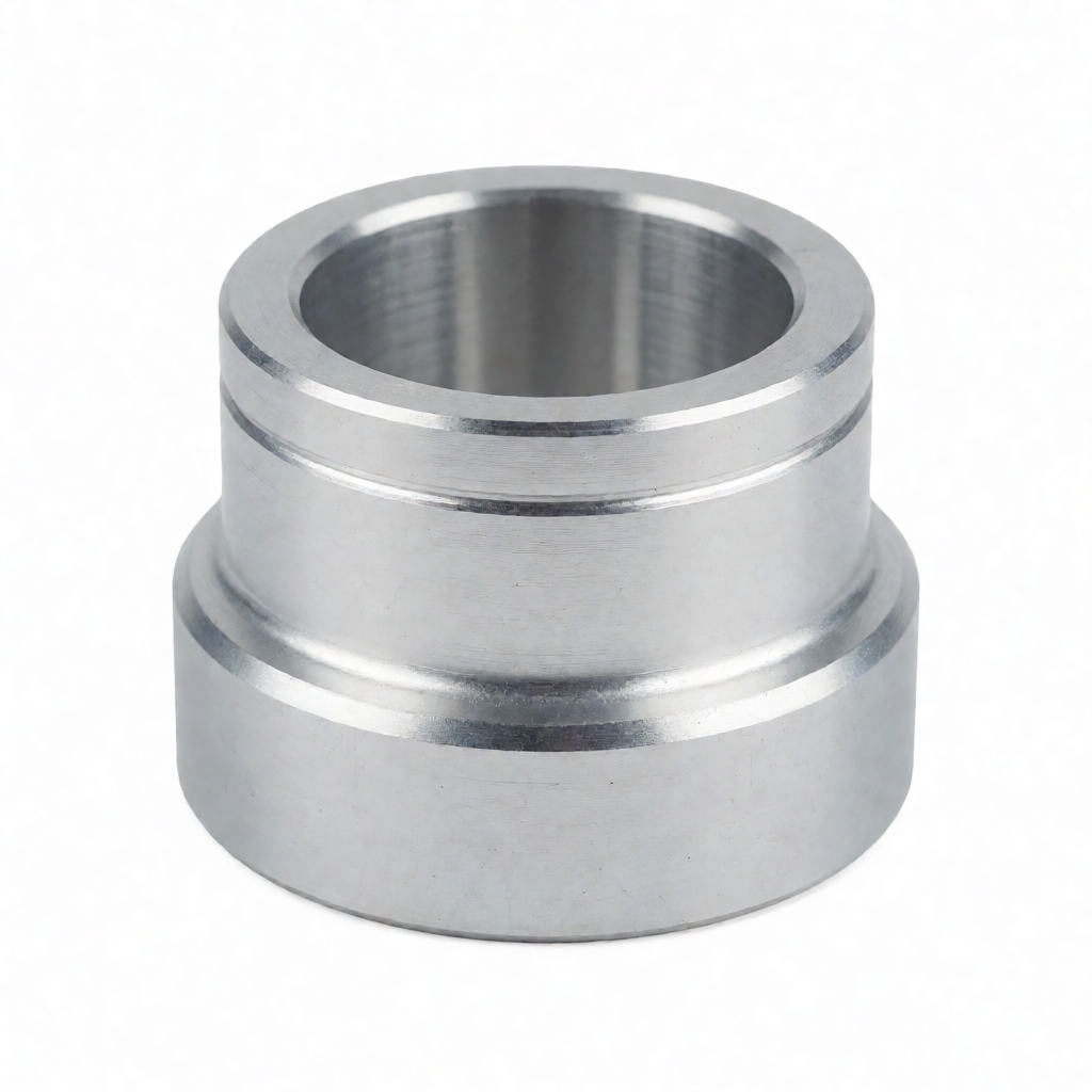
Core Logic of Lightweight Design for CNC Machined Robot Joint Arms
In the R&D of collaborative robots (Cobots) and high-end industrial robotic arms, lightweighting of CNC machined robot joint arms has shifted from a "nice-to-have" to a "must-have." The mass of the joint arms directly determines the peak torque requirements for motors, the stress-life of transmission systems, and the overall energy consumption of the unit. For technical procurement officers and engineers, understanding that lightweighting is not merely "weight reduction" but rather a process of reducing moment of inertia (J) and static mass through material substitution, topology optimization, and precision machining strategies, while ensuring structural stiffness and fatigue strength, is crucial. Taking a typical 7-axis robot base or forearm as an example, replacing traditional cast steel components with high-strength aluminum alloy parts machined via CNC milling can reduce weight by 30%–40%. This enables the use of lower-power servo motors and improves dynamic response speed. The following section analyzes how to achieve this goal through 5-axis CNC machining, based on practical manufacturing experience.
Material Selection: Feasibility and Parameters of Replacing Steel with Aluminum Alloys
The first step in lightweight design is material substitution. Although high-strength steels (such as 42CrMo4 or 4140) offer extremely high strength, their density (7.85 g/cm³) is nearly 3 times that of aluminum alloys (2.7–2.9 g/cm³). For non-critical load-bearing components like robot joint arms, high-strength aluminum alloys are often the superior solution.
- 7075-T6 Aluminum Alloy: Yield strength approx. 500 MPa, tensile strength approx. 570 MPa. Suitable for core load-bearing components such as bearing housings and motor mounting flanges with high strength requirements. Its hardness is HV95–101, and it has good CNC machinability, but attention must be paid to oxide film treatment to prevent corrosion.
- 6061-T6 Aluminum Alloy: Yield strength approx. 270 MPa, with excellent toughness and welding performance. Suitable for housings, heat sinks, and non-primary load-transferring structures. It has exceptional machinability and allows for high-precision dimensions (±0.01 mm level).
- Titanium Alloy Ti-6Al-4V: Density 4.43 g/cm³, high specific strength. Suitable for extreme lightweighting scenarios in aerospace-grade or medical robots, but high cost and significant machining difficulty (rapid tool wear, low-temperature cooling required).
In practical engineering, a "hybrid material" strategy is commonly employed: core load-transmitting arms are CNC milled from 7075 aluminum, while external decorative or non-load-bearing brackets are made from 6061 aluminum or engineering plastics (such as POM, PC). This combination allows for maximum weight optimization while controlling costs.
Structural Design: Topology Optimization and Hollowing Strategies
Simply changing materials is not enough; structural design must keep pace. Robot joint arms undergo alternating loads during high-speed operation, and traditional solid designs contain significant "redundant material."
Load-Based Cross-Section Optimization
Engineers must use Finite Element Analysis (FEA) to identify stress concentration zones and reduce the wall thickness of low-stress areas. For thin-walled components, 5-axis CNC machining centers can achieve complex internal cavity machining. For example, changing a solid cylindrical link to an internally hollowed tubular structure, while keeping the cross-sectional area constant, moves material distribution away from the neutral axis. This can actually increase bending stiffness while significantly reducing weight. Wall thickness is typically controlled between 3–5 mm to balance stiffness and machinability.
Lightweight Feature Design
- Chamfers and Fillets: All sharp corners must be treated with R2–R5 fillets to eliminate stress concentration factors. During CNC machining, attention must be paid to tool-tip radius limitations; overly small fillets (



