





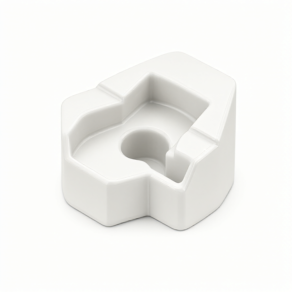
In the machining of precision CNC plastic parts, control over deburring and surface finish is the critical bottleneck determining part assembly accuracy, visual aesthetics, and the adhesion of subsequent plating or painting. Many buyers frequently encounter issues such as surface scratching, residual flash, or color inconsistency during the prototyping phase. This is rarely due to insufficient machine precision but rather a mismatch in tool strategy, feed parameters, and post-processing workflows. As a manufacturer with integrated injection molding and CNC capabilities, we understand that the chip sticking characteristics of engineering plastics (such as PEI, PPS, PA) during cutting far exceed those of metals. Based on batch production data from our 72 CNC machines, this article provides an in-depth analysis of the complete process chain from roughing to finishing, offering quantifiable solutions for flash removal and roughness control standards to help engineers mitigate batch consistency risks.
Cutting Characteristics of Engineering Plastics and Flash Formation Mechanism
Unlike the plastic shear of metals, thermoplastics exhibit an extremely high elastic deformation recovery rate during cutting. When the tool leaves the workpiece surface, the material does not undergo slight plastic flow as metal does; instead, it tends to spring back and tear, resulting in the phenomenon known as "chip sticking." This is the primary source of flash on plastic parts. The specific mechanism is as follows:
- Chip Sticking: Plastics have a low coefficient of friction, causing chips to easily wrap around the tool's relief angle. If chip evacuation is poor, the chips will recut the machined surface, producing secondary scratches and adhered flash.
- Tearing Effect: At corners or the edges of cavities, when tool radius is constrained, excessive depth of cut causes the material to be pulled rather than sheared, forming thin-sheet flash.
- Thermal Deformation: Plastics have poor thermal conductivity, leading to localized heat accumulation that causes material softening. This accelerates tool wear and amplifies surface waviness.
Therefore, simply increasing the spindle speed does not solve flash issues; it may even worsen chip sticking due to elevated cutting temperatures. Effective flash control must address both cutting parameters and tool geometry. In batch production, we typically use the flash occurrence rate of the first piece as a key quality indicator, aiming to control visible flash within a range invisible to the naked eye and ensure it does not affect subsequent surface treatments.
Impact of Key Process Parameters on Surface Finish
To achieve a surface finish of Ra 0.8μm or better, it is essential to strictly control the feed rate, spindle speed, and engagement angle. The following parameters are based on measured data from machining PA66 and PEI materials:
| Material Grade | Spindle Speed (rpm) | Feed Rate (mm/min) | Depth of Cut ap (mm) | Expected Roughness Ra (μm) | Key Control Points |
|---|---|---|---|---|---|
| PA66 | 8,000 - 10,000 | 300 - 450 | ≤ 1.0 | 0.8 - 1.2 | Requires strong cooling to prevent thermal chip sticking |
| PEI (PES) | 10,000 - 12,000 | 200 - 350 | ≤ 0.8 | 0.6 - 0.9 | Low depth of cut strategy to avoid compression |
| POM | 6,000 - 8,000 | 400 - 600 | ≤ 1.5 | 0.5 - 0.8 | Material is brittle; prevent chipping |
Data indicates that for most engineering plastics, the feed rate has a far greater sensitivity to surface roughness than spindle speed. For every 10% increase in feed rate, surface waviness deteriorates significantly. Furthermore, using climb milling rather than conventional milling significantly reduces scratching, as the tool engages from below the workpiece, reducing the energy required for material tearing. However, climb milling requires higher machine rigidity; backlash must be eliminated. For thin-walled parts, we recommend A "shallow-cut, high-pass" strategy limits the depth of cut per pass to within 15% of the tool radius, suppressing vibrations caused by cutting forces.
Tool Selection and Geometry Optimization Strategies
Tools act as the final physical defense line in determining the quality of plastic parts. Using generic tungsten carbide tools directly for plastic machining often results in high burr formation because their rake angle and chip-flute designs are not intended for low-hardness materials. Ideal plastic-dedicated tools should possess the following characteristics:
- High rake angle and sharp cutting edge: The rake angle typically needs to be above 15°-20°. A sharp cutting edge reduces the compression zone, allowing chips to be evacuated smoothly, preventing chip packing that would scratch the surface.
- Helix angle optimization: End mills with a high helix angle (40°-45°), single- or two-flute, shorten the contact time between chips and the finished surface, reducing the probability of chip built-up edge (BUE). For pocketing operations, three- or four-flute tools help balance radial cutting forces.
- Coating selection: PTFE (polytetrafluoroethylene) coatings or diamond coatings (limited to non-ferrous materials; high-hardness nanocoatings are commonly used on plastics) can reduce the coefficient of friction. For processing high-temperature materials such as PEEK, heat-resistant ceramic coatings are more reliable.
In practical operations, the end corner radius (Rend) is also critical. For parts requiring sharp edge features, Rend should be less than 0.1mm. For structural components requiring no stress concentration, increasing Rend to 0.2-0.3mm helps prevent edge chipping. We recommend performing trial cuts to verify tool performance before mass production, recording burr height at different feeds, and building a dedicated tool database for the specific material family.
Deburring Technique Comparison: Ultrasonic, Electrolytic, and Mechanical Methods
Direct CNC machining cannot eliminate all microscopic burrs; post-processing is essential. For plastic parts, common deburring methods each have their advantages and disadvantages; selection must consider part complexity and batch size.
| Process Method | Principle Overview | Application Scenarios | Limitations/Risks | Recommendation Index (1-5) |
|---|---|---|---|---|
| Ultrasonic Cleaning | Uses cavitation effects to strip fine chips | Shallow burrs, internal cavities, precision parts | Ineffective for thick flash; requires specialized solvents to remove adhered polymer | 4 | Plasma Treatment | High-energy beam vaporizes plastic edges | Miniature precision parts, optical components | High cost; may alter the molecular structure of edge material; requires strict energy control | 3 | Mechanical Grinding/Polishing | Removes excess material through abrasive friction | Large flat surfaces, outer contours, high-gloss required areas | Prone to overcutting; poor consistency in manual operations; not suitable for complex internal cavities | 4 |
| Cryogenic Crushing | Brittle fracture at low temperatures | High-volume recovery of scrap with simple shapes or edge treatment | Alters material properties; unsuitable for precision assemblies; high noise level | 2 |
In our production practice, ultrasonic + mechanical fine polishing is a high cost-performance combination. First, CNC machining leaves a finishing allowance of 0.1-0.2mm. Ultrasonic cleaning removes 80% of macroscopic burrs and oil stains, followed by local mechanical or chemical polishing (for specific plastics) on visible surfaces. For internal blind holes or shaped holes, the advantage of ultrasonic cleaning is irreplaceable because it penetrates areas unreachable by conventional tools. Note that different plastics have selectivity regarding ultrasonic cleaning solutions. For example, PC-based materials in alkaline solutions are prone to yellowing; neutral or weakly acidic cleaning solutions should be used, and temperature must be controlled below 40°C to prevent thermal deformation.
Surface Consistency Control in Mass Production
A qualified prototype does not guarantee stable mass production. Fluctuations in the surface gloss of plastic parts often stem from cumulative tool wear or material batch variations. To achieve batch delivery within 15-25 days while maintaining high surface finish consistency at Ra 0.4μm, full-process monitoring must be established:
- Tool life management: Set a part-count threshold for each tool (e.g., PA66 flat-end mills require regrinding or replacement every 50 parts). Monitor spindle load in real-time l. When the cutting current increases by 5%–8%, force a tool change to prevent surface bauling caused by a dull tool.
- Material Pre-Treatment: Injection-molded parts must be thoroughly annealed to relieve internal stresses. CNC stock materials must rest for more than 24 hours to stabilize. The moisture content or hygroscopicity of materials (such as POM or PA) must be controlled within specified limits; otherwise, dimensional drift will occur due to volume changes during machining.
- Toolpath Verification: Use CAM software to simulate cutting operations to check for self-collisions and air cuts. For high-gloss surfaces, adopt a “trochoidal milling” strategy. By using a smaller Z-axis depth of cut and maintaining a constant cutting edge length, uniform texture direction is achieved.
In addition, controlling the workshop environment with precise temperature and humidity regulation is critical. A 1°C temperature fluctuation can cause dimensional variation of 0.02–0.05 mm in precision plastic parts. Our machining shop maintains a 22±1°C environment in the precision machining area. Upon completion of machining, immediate online dimensional sampling inspections are performed using combined verification via a Coordinate Measuring Machine (CMM) and a roughness tester to ensure both aesthetic and functional standards are met.
Frequently Asked Questions (FAQ)
How do you resolve severe tool welding and rough surfaces when CNC machining PEEK?
PEEK has a high melting point and strong adhesion. It is recommended to increase the spindle speed to 12,000–15,000 rpm, drastically reduce the feed rate to 100–200 mm/min, and use specialized PEEK tools with large rake angles and high helix angles. Simultaneously, activate high-pressure cooling (liquid or air) to prevent excessive heat in the cutting zone, which exacerbates adhesion. If residue persists, combine ultrasonic cleaning to remove microscopic adhered material.
How to achieve a mirror finish (Ra < 0.1 μm) on plastic parts?
Direct CNC machining typically achieves only Ra 0.4–0.8 μm. To achieve a mirror effect, a 0.1 mm polishing allowance must be reserved after CNC machining, followed by precision chemical polishing or vibration lapping. This requires the material to be free of inclusions and the surface to have no deep scratches. For POM, high gloss can be achieved through specific chemical solvent polishing, but the immersion time must be strictly controlled to prevent dimensional overrun.
Why do thin-walled plastic parts warp and have enlarged burrs after machining?
Thin-walled parts have low rigidity, making them susceptible to deformation from cutting forces. If clamping pressure on the contact surfaces is uneven, elastic recovery after unclamping will alter the part’s shape. Enlarged burrs are typically caused by chatter (machine tool vibration) due to lack of support at the exit side of the thin wall. The solution is to use hydraulic flexible clamps for even pressure application, employ support fixtures on the exit side, and reduce the depth of cut to less than 0.5 mm, completing the operation in multiple passes.
Which surface treatment processes are suitable for plastic parts that have already been de-burred?
Surfaces after de-burring are usually relatively clean, making them suitable for spraying, plating, or anodizing (limited to conductive plastics or metal-composite parts). For ABS and PC, flame or plasma treatment is required before spraying to enhance adhesion. For non-polar materials like PP, corona treatment is necessary. Direct plating is generally used for PBI or specially modified plastics, requiring a surface roughness of less than Ra 0.2 μm to ensure a uniform coating.
How to determine if burrs have been completely removed without affecting assembly?
In addition to visual inspection, it is recommended to observe edges using a 10–20x magnifier. Functionally, if the part requires a precise interference or transition fit, even 0.05 mm of residual burr can cause assembly jams or stress concentration. The standard practice is to perform a trial assembly test; if there is any resistance or jamming felt by hand, the part is deemed non-conforming. For mass-produced items, optical projectors can be used to inspect edge profiles to confirm the absence of protruding points.
Conclusion and Recommendations for Action
Machining precision plastic parts is not just about optimizing cutting parameters; it is a systematic engineering process involving material properties, tool geometry, and post-processing workflows. By optimizing climb-milling strategies, utilizing specialized tools with large rake angles, and combining this with ultrasonic cleaning, surface finish can be consistently controlled at the Ra 0.4 μm level, effectively eliminating macroscopic burrs that affect assembly. Relying on 72 CNC machines and a comprehensive inspection system, ShowyMetal provides a one-stop solution for customers from DFM (Design for Manufacturability) to mass production delivery, ensuring high standards of aesthetic quality and dimensional accuracy within a 15–25 day lead time.
If you are developing products with precision plastic components or are facing surface consistency issues with your current suppliers, please send us your drawings and technical specifications. Our engineering team will provide a feasible process assessment and quote within 24 hours to help you mitigate mass-production risks.



