





Multi-axis Tool Path Strategy Challenge in CNC Machining of Complex Surfaces
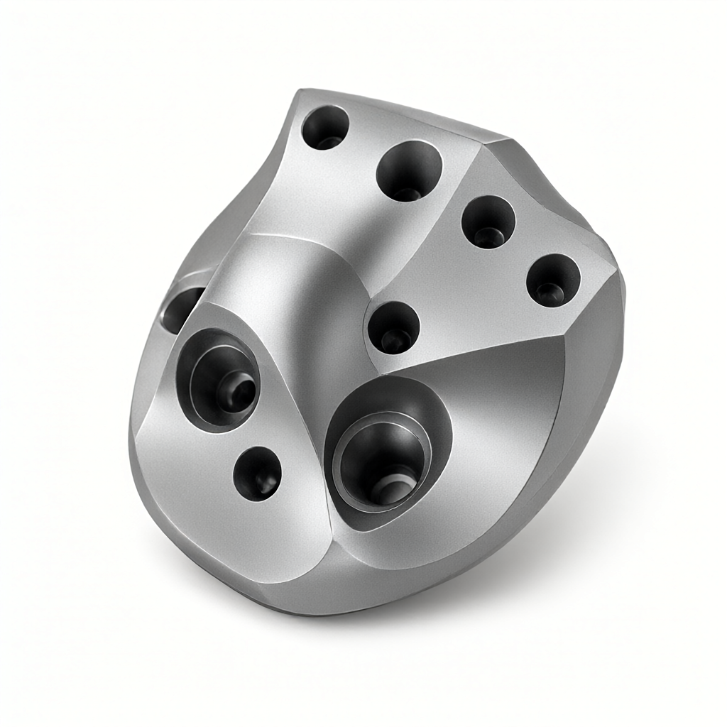
Freeform surfaces are used in the design of aerospace structures, medical implants and high-end communications equipment. Free-form Surfaces and deep cavity thin-wall features are becoming increasingly popular. Traditional three-axis machining of these parts faces core pain points such as tool interference, excessive cantilever length and difficulty in controlling residual surface height. Multi-axis CNC machining can significantly reduce cutting forces, improve surface integrity and shorten manufacturing cycles by cooperatively controlling the attitude of the five-axis space. However, multi-axis tool path strategy is not a simple coordinate superposition, but involves kinematics singularity avoidance, tool attitude optimization, material removal rate balance system engineering. For technical procurement and R & D engineers, evaluating the multi-axis capability of suppliers should not only look at the number of equipment, but also need to go deep into their tool path planning logic and process validation data.
Five-axis linkage principle and core logic of tool path planning
A 5-axis machine tool (usually consisting of 3-axis linear drives plus 2 rotating axes) allows the tool axis to rotate relative to the workpiece, thus maintaining the best cutting angle at all times. For complex surfaces, the main tool path strategy consists of the following three modes, the underlying logic of which determines the final part accuracy and efficiency.
Trochoidal Milling and Steep Area Processing
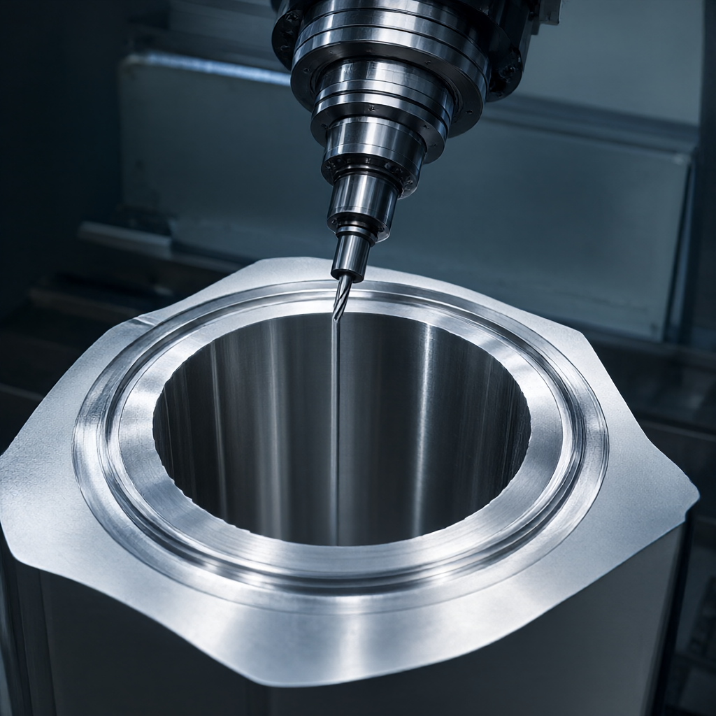
The traditional spiral or radial step tool path is easy to occur "tool root effect" when the depth of cut is large and the radial feed is small, resulting in tool collapse. When dealing with deep cavity bottom or vertical steep sidewall, the five-axis machine tool can tilt the spindle to make the tool participate in cutting with a larger contact area, avoid excessive lateral force, and effectively avoid geometric interference. This strategy is particularly critical in titanium alloy and high temperature alloy machining.
Point Drive and Surface Drive
The point-driven method generates tool paths based on discrete points of mesh model, which is suitable for structural parts with complex topology but no strict surface continuity requirements. The calculation speed is fast but the risk of overcutting is easy to occur. The surface-driven method generates tool paths along the normal direction of the design model surface, which can ensure the residual material amount of the surface. Precision control of Scallop Height is the preferred strategy for high-precision curved parts such as aerofoil blades and optical molds. In actual production, it is often necessary to combine two methods in CAM software, using surface drive for smooth areas and point drive for deep cavity bottom.
Engineering trade-off between material removal rate and tool pose optimization
The core advantage of multi-axis machining lies in "attitude freedom", but it is not that the more flexible the attitude, the higher the efficiency. In engineering practice, the following parameters need to be weighed:
- Tool Tilt Angle: Usually set between 30°-60°. Too small inclination angle, tool overhang, vibration, surface roughness deterioration; too large inclination angle, tool holder impact risk increases. For aluminum alloy, 50° inclination angle can often achieve better surface finish and cutting force balance; for steel materials, it is recommended to control around 30° to enhance rigidity.
- Tool Length and Overhang: Five axes allow the use of short tools and long tool holders, so that the cutting point is far away from the center of rotation and the radial overhang is reduced. The overhang ratio is controlled within 1.5:1, which can significantly increase the natural frequency of the system and avoid surface ripples caused by chatter.
- feed speed synchronization: When multi-axis linkage, the feed speed of the five axes must be strictly synchronized. If the rotational axis speed is slower than the linear axis, it will cause "broach" stripes on the surface; otherwise, it is easy to produce sudden stop bending, resulting in surface micro-cracks. The "Kinematics Optimization" module in CAM software is very important. It can adjust the speed distribution of each axis in real time to avoid exceeding the interpolation limit of the machine tool.
Influence of Different Tool Geometry on Surface Quality
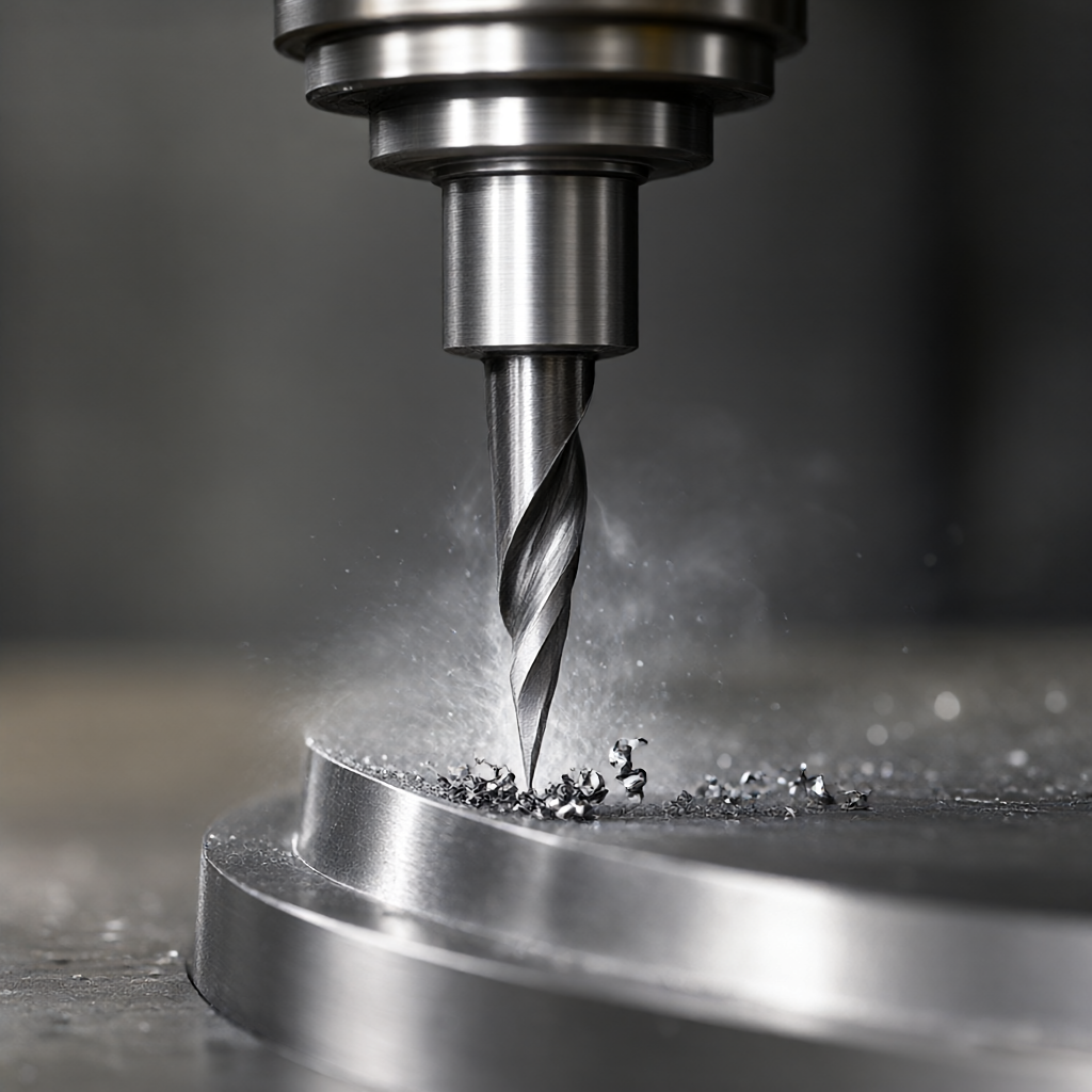
Tool selection directly determines the residual height and machining efficiency. Ball Nose is standard for surface machining, but its contact area varies with radius, resulting in extremely low removal rate of the tip area. To solve this problem, the industry generally adopts the following two improvements:
| tool type | surface adaptability | material removal rate | Surface roughness control | typical application scenarios |
|---|---|---|---|---|
| standard ball cutter | Excellent (global coverage) | Low (poor efficiency in tip area) | High (no knife marks) | Complex organic surfaces, mold finishing |
| V-shaped ball head/horn knife | Good (need to be treated by zones) | Medium-high (large contact surface) | Medium (needs finishing) | Rough and semi-finish machining of aerospace structural parts |
| Flat-bottomed V-knife | Medium (local only) | High (at specific angles) | ordinary | Deep cavity bottom cleaning |
For mass production that pursues efficiency, using a large-diameter V-shaped tool for rough machining, and then using a small-diameter ball-nose tool for corner cleaning and finish machining is a classic "two-tool strategy." This combination can not only take advantage of the high removal rate of large tools, but also ensure size accuracy at sharp corners with small tools, which can usually shorten the total processing time by 30%-40%.
Key Process Parameter Setting and Vibration Suppression
Vibration (chatter) in multi-axis machining is the main killer of surface quality. Engineers need to set parameters according to the dynamic stiffness of the tool-workpiece-machine system. Generally speaking, in aluminum alloy machining, most resonance zones can be avoided when the spindle speed is set at 12000-15000 rpm and the feed per tooth is 0.1-0.2 mm. If periodic ripples appear on the surface, the spindle speed should be reduced immediately or the feed per tooth should be adjusted instead of simply modifying the tool path. In addition, the choice of Rake angle is also crucial: positive rake angle helps to remove chips, reduce cutting force, suitable for soft materials such as aluminum and copper; zero or negative rake angle provides higher rigidity, suitable for difficult machining materials such as stainless steel.
Acceptance criteria and test methods for surface quality
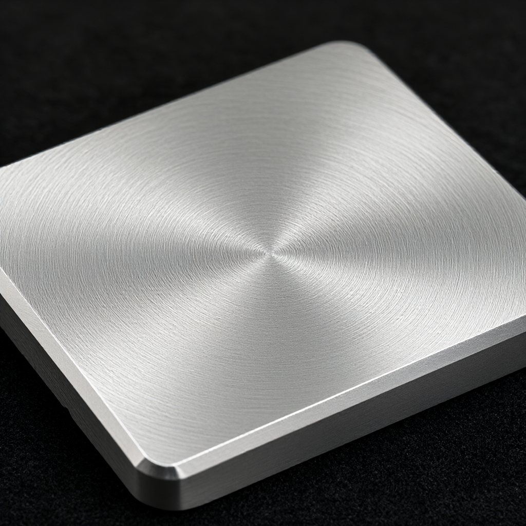
When the purchaser accepts complex curved parts, he cannot rely solely on visual inspection. A quantitative acceptance system must be established:
- Coordinate Measurement (CMM): Scan the surface with a ball bar or laser probe to evaluate form and position tolerances. For surfaces with Ra <0.8μm, CMM point density must be ≥ 5 points/mm² to accurately capture small deviations. Focus on detecting size deviations in areas with large curvature changes.
- Surface Roughness Tester: Take samples in the vertical direction of cutting direction to evaluate Ra value. Pay attention to distinguish between "process roughness" and "microscopic defects of material itself", the latter needs to be judged by microscope. Ra 0.4μm usually requires finishing allowance control in 0.05-0.1mm, and high-speed finishing or finishing milling strategy is used.
- interference verification: Suppliers are required to provide NC code simulation screenshots of post-processing to demonstrate that there is no physical collision between tool holder and workpiece holder at a minimum overcut setting of 0.01mm. This is key evidence to evaluate their CAM software capabilities and process rigor.
Frequently Asked Questions (FAQ)
5-axis machining compared to 3-axis machining, in terms of cost advantage reflected in what?
5-axis machines and tools cost a lot, but their individual man-hours are greatly reduced. For deep-cavity, multi-angle features, 5-axis can reduce clamping times (one-time clamping to complete multi-surface machining), reducing the cumulative error caused by secondary positioning and fixture costs. In mass production, 5-axis high scheduling flexibility helps balance multi-variety mixed flow production, improving overall capacity utilization.
How to judge whether the supplier's multi-axis tool path is reasonable and avoid "false five-axis"?
"False 5-axis" refers to only using 5-axis machine tool to do 3-axis machining, or simply taking the rotating axis as the fifth axis without linkage logic. Ask the supplier to provide CAM software post-processing log, observe whether the G code contains S (speed) of multiple axes and synchronous interpolation instructions for X/Y/Z and A/B/C axes. At the same time, ask if they have performed tool attitude optimization analysis and can explain the selection basis of specific area inclination angle. A true multi-axis process needs to be globally optimized by combining the workpiece model, tool library and machine kinematics constraints.
What process risks should be paid special attention to when machining titanium alloy complex surfaces?
Titanium alloy thermal conductivity is poor, cutting heat is easy to accumulate, resulting in rapid tool wear and even "tool sticking" to scrap parts. Must use large flow of cutting fluid cooling, and strictly control the spindle power load. Tools need to choose coated carbide, and rake angle should be large to reduce cutting force. Process should be used large diameter, multi-edge, small edge diameter tool combination, maintain high speed and low feed, avoid tool and machined surface friction. Acceptance needs to increase tool life monitoring records to ensure batch consistency.
What is the minimum feature size? Can we achieve no contact marks?
In conventional 5-axis machining of aluminum alloys, the minimum feature size is typically up to 0.5mm radius. With a reasonable tool path overlap strategy (Overlap 5%-10%) and high spindle speeds, theoretical mark-free can be achieved. However,"mark-free" is a dynamic process that needs to be set in combination with material removal rate and surface roughness requirements. For extremely high finish requirements (e.g. optical components), additional polishing steps may be required rather than relying solely on cutting.
How to ensure the consistency of multi-axis parts in mass production?
Consistency depends on fixture repeatability, tool compensation value monitoring and CAM program stability. Tool life management system must be established, automatic replacement or regrinding every N pieces machined, and re-measurement of compensation value. Fixture should use precision profile fixture or vacuum adsorption to reduce human interference. 100% of the key size is checked before shipment, and CMM scanning data is kept for future reference. Factory with perfect process control system, its batch size fluctuation can be stabilized within ±0.02mm.
Conclusion and recommendations for action
Multi-axis CNC machining of complex surfaces is a systems engineering involving deep coupling of tools, machines, CAM strategies and materials science. As a technical procurement or R & D engineer, you should not only pay attention to the number of equipment, but also examine the supplier's tool path planning capabilities, vibration control experience and quality traceability system. ShowyMetal has 72 multi-axis CNC machines, supporting ±0.01mm accuracy and Ra0.4μm surface finish, providing one-stop service from DFM advice to batch consistency control. If you have complex surface parts machining challenges, welcome to send 3D drawings and technical requirements, our engineering team will customize your own tool path strategy and rapid quotation plan.



