Core Definition and Judgement Basis of CNC Turning Surface Roughness Standard
In the field of precision manufacturing, CNC turning surface roughness is a key indicator to determine the friction, sealing, wear resistance and appearance quality of parts. For technical procurement and engineers, the first step to avoid acceptance disputes is to clarify the criteria for roughness parameters. In the internationally accepted surface texture parameter system, the arithmetic average height Ra is the most commonly used indicator, which represents the average depth of surface microscopic geometric undulations. In addition, the maximum height Rz and the ten-point height R10 are often used as auxiliary parameters to monitor local peaks and valleys on the surface. According to ISO 21920-1:2013, in general mechanical structures, Ra values for machined surfaces are usually controlled between 1.6μm and 0.8μm; while in precision mating surfaces or hydraulic sealing surfaces, Ra values are often required to be reduced to 0.4μm or even 0.2μm. Understand that these parameters are not simple values, the smaller the better, too small roughness will increase the processing cost and may reduce the oil storage capacity under specific conditions, so it is necessary to combine the parts function for reasonable setting.
Four Technological Factors Affecting Surface Roughness in CNC Turning
Surface quality is not determined by a single variable, but by the interaction of cutting parameters, tool condition, workpiece material and machine stiffness. An in-depth analysis of these factors helps predict and optimize surface results during the process planning phase.
- Cutting parameters:Back cut ap directly determines the depth of residual ripple. In the finishing stage, ap is reduced to less than 0.05mm, with higher feed speed, Ra value can be significantly improved. However, too high cutting speed vc will lead to increased tip temperature and increased tool wear; too low is easy to produce chip accumulation, resulting in surface tearing. It is necessary to find a balance point within the recommended cutting speed range of the material.
- Tool geometry and wear:The radius re of the tool tip arc is the key to determine the theoretical roughness. The larger re, the farther the actual cutting point is from the theoretical cutting point, the smaller the theoretical residual area, and the smoother the surface. Meanwhile, the tool tip wear VB will directly change the cutting trajectory, and the surface roughness will deteriorate sharply when the wear exceeds the limit.
- Workpiece material characteristics:High hardness steel, stainless steel and titanium alloy due to good toughness, strong tendency to work hardening, turning easy to stick tool or burr, surface quality sensitivity is higher than aluminum alloy. Engineering plastics are easy to melt due to poor thermal conductivity adhesion, special attention should be paid to cooling methods.
- Machine tool rigidity:The vibration of the machine tool itself will leave high frequency ripples on the workpiece surface. Under the same parameters, it is often difficult for a less rigid machine tool to obtain a lower Ra value than a more rigid machine tool, especially in high-speed turning.
Comparison of Surface Roughness Parameters of Common CNC Turning Materials
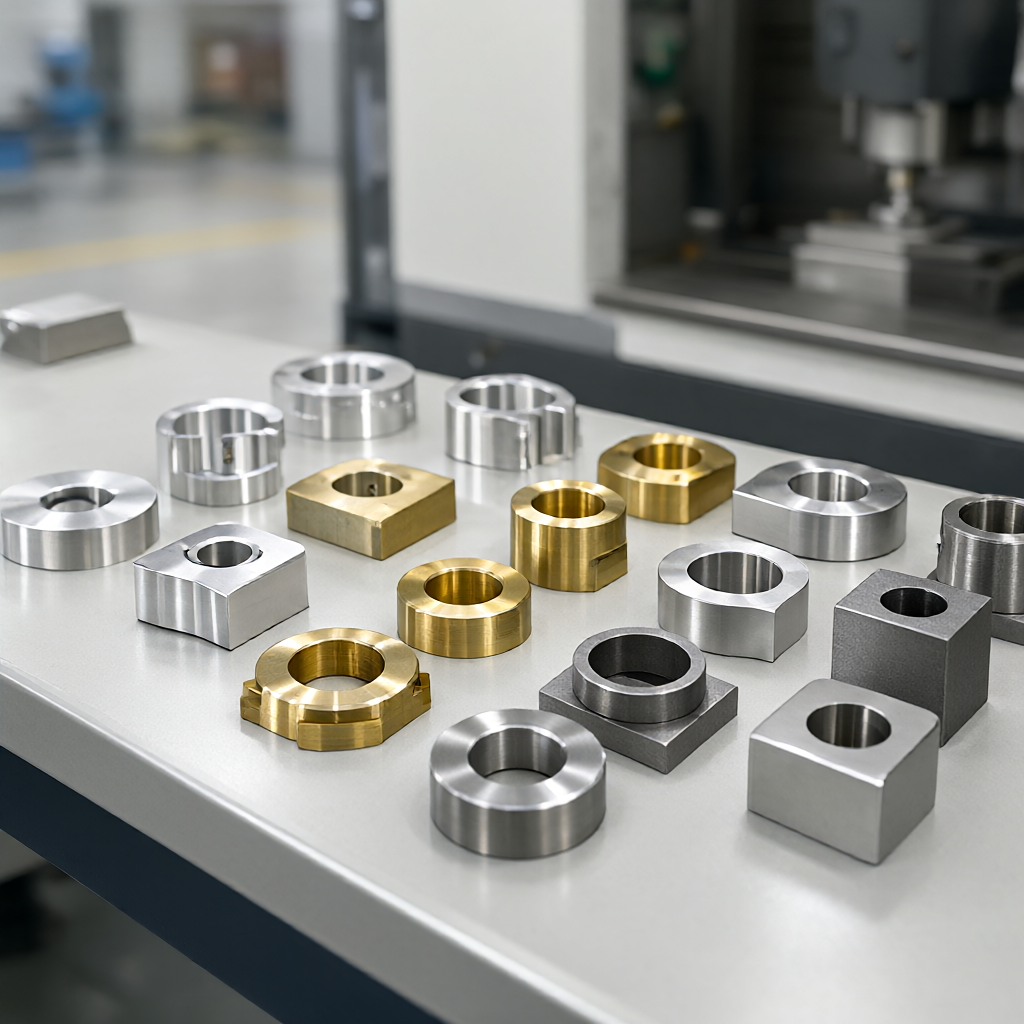
The cutting behavior of different materials in CNC turning is very different, which directly affects the final upper limit of surface quality. The following table summarizes the reference range of surface roughness that can be stably achieved by common materials under standard turning technology and the best applicable conditions. These data are based on the experience values of general cemented carbide tools and conventional cutting fluid conditions.
| material categories | Typical grade/material | Conventional turning Ra (μm) | Finishing/Polishing Ra (μm) | Key Factors Affecting Surface Quality |
|---|---|---|---|---|
| aluminium alloy | 6061-T6, 7075-T6 | 0.8 - 1.2 | 0.2 - 0.4 | Low cutting speed sensitivity, easy to obtain smooth surface; need to prevent aluminum chips from winding caused by scratches. |
| carbon steel/stainless steel | 45#steel, 304/316L | 1.2 - 1.6 | 0.4 - 0.8 | Good toughness, easy to stick tool;316L machining hardening strong, need high rigidity machine tool and large rake angle tool. |
| copper alloy | H62 brass, T2 copper | 0.8 - 1.0 | 0.2 - 0.4 | Excellent ductility, easy to stick tool; need to use large back angle, large rake angle tools and increase the flow of cutting fluid. |
| engineering plastics | PEEK, PTFE, PBT | 0.8 - 1.6 | 0.4 - 0.8 | High heat sensitivity, easy to melt adhesion in dry cutting; wet cutting or reducing feed rate is recommended. |
It can be seen from the table that aluminum alloys and copper alloys are usually more advantageous than stainless steel in surface roughness control because of their small cutting force and difficulty in hardening. For engineering plastics, although the theoretical roughness can reach a lower level, the process stability depends on the cooling medium.
Three Main Methods of Surface Roughness Inspection in CNC Turning
"Uncertainty" is the pain point in appearance and accuracy acceptance of many factories. Choosing the correct measurement method is not only related to data accuracy, but also related to measurement efficiency. At present, the industry mainly uses stylus, optical non-contact and laser confocal three detection methods, each has its advantages and disadvantages.
stylus surface roughness tester
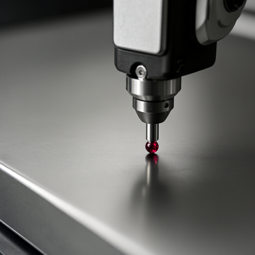
This is the most widely used and relatively controllable detection method. Through the ruby stylus across the workpiece surface, the sensor picks up the electrical signal of the needle moving up and down, and obtains Ra, Rz and other parameters through integration. Its advantage lies in its good adaptability to metal surfaces, stable measurement values, and compliance with ISO 4287 standards. The disadvantage is that the contact measurement will be on extremely precise surfaces (such as Ra).