





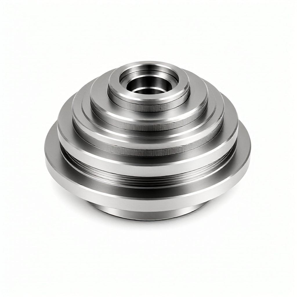
Complex CNC turning part design: key points to avoid interference and deformation. In precision manufacturing, many scrap due to interference jamming or thermal deformation stem from early design omissions. This article analyzes the effects of rigidity, tool path and heat dissipation on turning accuracy, and provides engineering-level avoidance strategies.
Analysis of the Core Causes of Interference and Deformation
tool interferenceIt refers to the physical collision between the tool path and the machined surface of the workpiece, fixture or machine tool structure during the turning process. Common in slender shaft parts or complex profiles with deep cavities. Interference directly leads to tool breakage or machine alarm, interrupting production.
Thermal deformation and tool yield effect
Cutting heat causes local temperature rise of workpiece, thermal expansion coefficient difference causes size drift, cutting force causes elastic deformation of slender workpiece (tool yield), shrinkage after cooling causes size out of tolerance. The superposition of these two physical phenomena is the main reason why it is difficult to control the stability of high-precision turning parts.
Aspect Ratio Design Limitations and Rigidity Optimization
toNC turningMachining, the length to diameter ratio (L/D) of the workpiece directly determines the processing stability. General principles: 3-axis lathe processing L/D less than 5; increase the center frame can be extended to 8; centering or milling compound can reach more than 10. If the L/D exceeds 8, auxiliary support (center frame/high level) must be introduced or the structure modified.
If there are deep holes or blind grooves in the workpiece, the vibration and thermal stress in the cutting process will be significantly amplified when the wall thickness is less than 10% of the aspect ratio. It is recommended to increase the wall thickness of non-critical parts to 0.8-1.0mm or more, or release the stress by graded rough finishing.
Tool Path Planning and Interference-free Programming
writeturning-processing programWhen turning a bore or stepped shaft end, the tool withdrawal path must have sufficient allowance (usually greater than the tool radius +0.2mm).
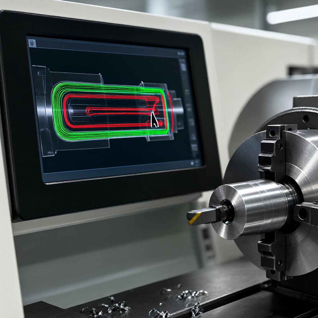
- Profile tool radius compensation:Avoid sharp corner collision, chamfer C0.5 above; if must go sharp corner, need to separate feed for many times.
- Tool change point Settings:Away from the workpiece surface, set aside 3-5mm safety clearance, prevent scratch when changing the tool has been machined surface.
- Benchmark of tool setting:Establish a unified coordinate origin to avoid interference caused by accumulated error caused by datum transformation.
Tool selection, cooling and thermal control strategies
Tool selection directly affectsdeflectionCemented carbide inserts (such as YG8/YG6) have high cutting speed but poor thermal conductivity, while high speed steel (HSS) has good thermal conductivity but weak strength. Diamond coated inserts are often used to reduce cutting heat when machining aluminum alloy parts.
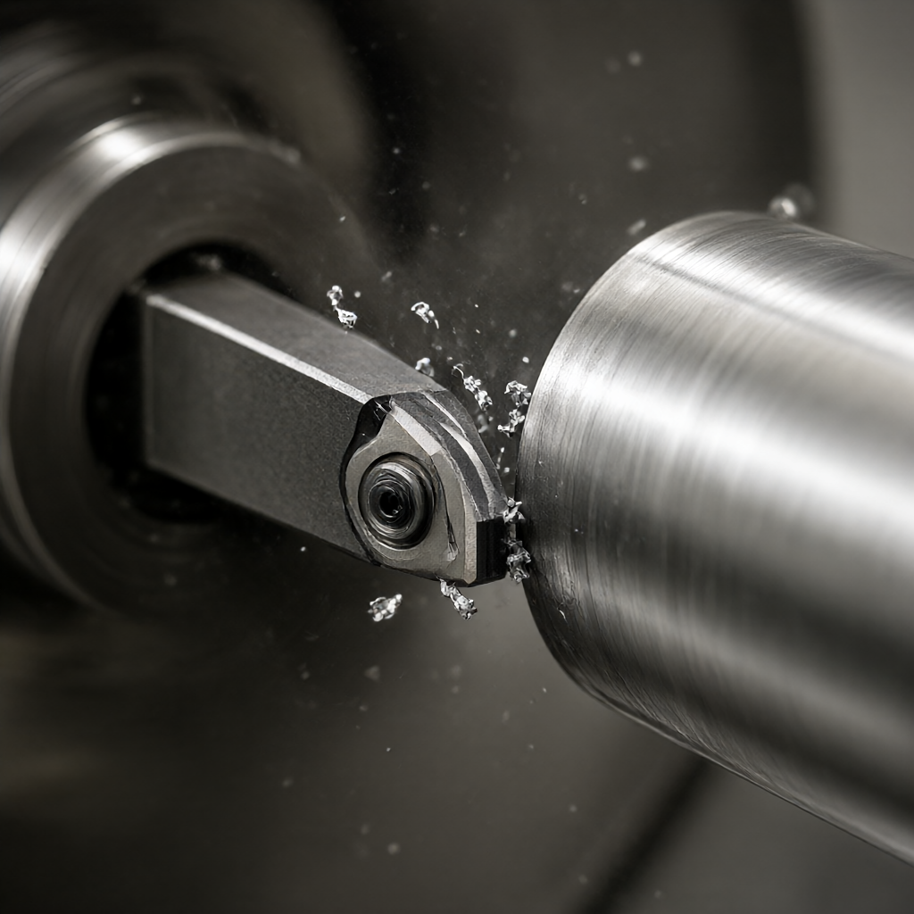
Cooling, high-pressure micro-lubrication (MQL) in the processing of titanium alloy or heat-resistant steel is better than a large number of cutting fluid. Although a large number of cutting fluid cooling fast, but the workpiece surface temperature shock will lead to residual thermal stress, resulting in deformation of turning parts. Reasonable control of feed rate and back turning amount (ap), to maintain a stable cutting force, is the key to reduce the knife.
Comparison of Turning and Turning-milling Combined Schemes
In the face of complex parts, pure 3 axis/4 axis turning may not be able to avoid interference, need to introduce 5 axis turning milling compound. The following table compares the two differences in interference control and deformation management:
| Compare Dimensions | 3/4 axis CNC lathe | Five-axis turning-milling compound machine tool |
|---|---|---|
| risk of interference | High. Tool in/out path is limited, easy to collide with the workpiece/fixture | Low. B-axis/C-axis linkage, can avoid the machined surface at a large angle |
| control of workpiece deformation | Depending on fixture design (center frame), residual stress release is slow | One-time clamping to complete multi-surface turning, uniform stress distribution, small deformation |
| Applicable parts | Stepped shaft, sleeve type, simple special parts (L/D< 5) | Complex shells, aviation joints, polyhedral parts (L/D > 8) |
| upper limit of machining accuracy | ±0.02mm (without auxiliary clamping) | ±0.01mm (after thermal compensation) |
Conclusion:When the part involves multi-directional grooves, chamfers or complex surfaces, if the 3-axis turning interference verification does not pass, it should be directly upgraded to a turning-milling compound scheme. Although the cost of a single piece is slightly higher, it can save the accumulated error caused by multiple clamping.
Practical points: DFM review and first article verification
DFM (Design for Manufacturability) review is the last line of defense against interference and distortion hazards during the engineering docking phase. The following parameters need to be checked:
- Minimum sharp corner radius:Turning inner sharp corner must be R0.5 or above, otherwise the tool can not be formed and easy to break edge.
- Heat sink/lightening slot:Symmetrical cooling grooves are designed on thick-walled parts (>20mm) to reduce warpage after cooling.
- Datum reservation:The grinding/finishing allowance (0.3-0.5mm) shall be reserved for the critical size surface to avoid the stress in rough turning stage directly reflected on the final size.
When processing the first piece, it must be carried outprocess control inspection: In addition to three-coordinate full size detection, it is necessary to detect the deformation difference between the natural state and the clamped state of the part (rebound amount after loosening). If the rebound amount is>0.01mm, it is necessary to modify the clamping force or adjust the fine turning parameters (such as reducing the back cutting amount to 0.05-0.1mm and reducing the feed amount to 0.05mm/rev).
Frequently Asked Questions (FAQ)
How do complex CNC turning parts determine whether a center frame is needed?
The rule of thumb is that when the free length of the part (the distance between the two main support points) exceeds 5 times its minimum diameter, or when the tool vibration is obvious during machining, the center rest must be used.
Processing heat-resistant alloy turned parts is severely deformed, how to reduce it?
Titanium alloy, Inconel and other low thermal conductivity materials are easy to store heat. It is recommended to use large feed/small back cut to maintain cutting force, supplemented by high pressure micro-cooling directly aligned with the tip. The feed rate in the finishing stage needs to be reduced to 0.02-0.03mm/rev to control the surface thermal stress.
How to avoid scratching the machined precision surface when changing tools?
Use the tool change point of quick positioning (G00) in the program. This point must be set within the safety clearance of the tool rotation axis and at least 5mm away from the workpiece surface. At the same time, set the safety height of the tool magazine opening/closing action to prevent interference with the tool arm.
Is it a problem of machine tool accuracy to bend after turning slender shaft?
Not necessarily machine accuracy. 90% of the case is the release of elastic deformation (tool) or thermal deformation. It can be verified by improving the fixture (such as hydraulic three-jaw + tail high level), increasing the fine turning path allowance, or standing for 24 hours after machining (after stress release).
Can you completely avoid interference by modifying the design?
Yes. Change complex deep grooves to step shapes, increase tool feed angles (e.g. 15° lead angle), or change sharp corners of non-mating surfaces to chamfers/fillets. Be sure to perform Clash Detection with CAM software before issuing design drawings.
Conclusion and recommendations for action
Avoid turning interference and deformation, need toDesign, programming, machining, inspectionFour stages of synergy. ShowyMetal is equipped with 72 3/4/5 axis CNC machines and walk-through machines. It can provide DFM interference review and machining plan comparison for ±0.01mm accuracy and high gloss batch requirements. If you have CNC turning drawings with large length and diameter, sensitive to thermal deformation or complex spatial interference, please send the drawings and process requirements to the engineering department. We will provide detailed manufacturability evaluation and batch delivery plan (regular batch delivery is 15-25 days).



