





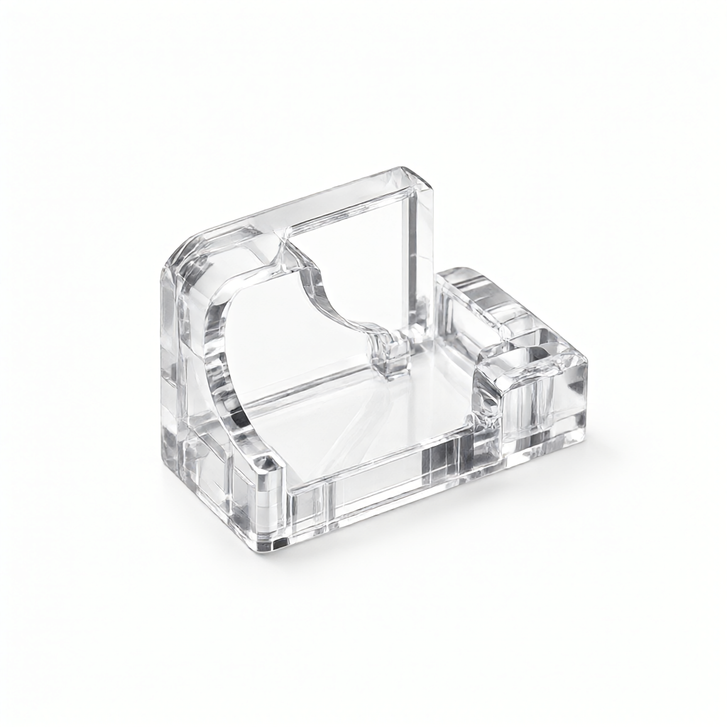
Transparent PC Custom CNC Parts Stress Crack Risk Sources and Avoidance Principles
In precision CNC machining, transparent polycarbonate (PC) is widely used for optical windows, sensor shields and communication components due to its high transmittance and toughness. However, PC is prone to internal residual stress during milling, drilling and subsequent processing, resulting in late stress cracking.(Stress Cracking), which seriously affects the product life and appearance consistency. As a core problem that both engineering technology and procurement need to recognize, stress cracking is not a simple material defect, but a result of the synergy of processing parameters, clamping methods, thermal management and surface treatment. This paper will disassemble the stress generation mechanism and provide executable process avoidance strategies and acceptance criteria.

Correlation between failure modes of PC stress cracking and material properties
The chemical resistance and stress release characteristics of transparent PC are key variables that determine the risk of cracking. When there is unreleased freezing stress inside the part, contact with solvents such as acetone, ethanol, methanol, or post-treatment such as plating or anodization will initiate crazing or even penetrating cracks along stress concentration areas (such as sharp corners, drill edges, and pinch marks).
- Residual stress sources:Milling cutting force results in plastic deformation of the bottom layer of the material, rapid cooling makes the surface layer compressed and the subsurface layer tensioned.
- Geometric stress concentration:The stress concentration coefficient Kt at sharp corners with R angle less than 0.5mm can be higher than 3.0.
- Solvent Attack:PC is sensitive to ketones and halogenated hydrocarbons, and cleaning agents or coatings containing such solvents can induce environmental stress cracking (ESC).
Influence of Precision CNC Machining Parameters on Stress Control
Reasonable setting of cutting parameters is the first line of defense to reduce residual stress. For transparent PC, the strategy of "light cutting, high row, slow advance" should be adopted to avoid heat accumulation and severe plastic deformation. The following is the recommended process window:
| parameter items | conservative recommendation | radicalization risk value | influence on stress |
|---|---|---|---|
| speed of mainshaft | 20,000-30,000 rpm | >35,000 rpm | Excessive heat input leads to a sudden increase in heat input and exacerbates freezing stress |
| feed speed | 500-800 mm/min | >1,200 mm/min | Excessive heat replacement, surface roughness deterioration, stress concentration |
| Each knife eats the knife quantity | ≤0.5 mm | ≥1.0 mm | The residual stress of the substrate increases significantly with the increase of cutting force |
| cooling method | Dry or Micro Lubrication (MQL) | Large quantities of water-soluble coolant | PC has a high water absorption rate, and the penetration of coolant into pores can easily induce later expansion and cracking. |
In addition, tool selection is critical. Coated carbide end mills are recommended, with rake angles of 10°-15° to reduce radial forces, and edge passivation radii controlled within 0.05mm to ensure no scratches on the surface of transparent parts and uniform micro-stress distribution.
Comparison of clamping technology and stress-relieving heat treatment scheme
Stress relief after machining is the core link to prevent failure. Different schemes have significant differences in efficiency, accuracy retention and application scenarios, and should be selected according to part size and tolerance requirements.

| stress relief scheme | process principle | range of application | advantages and disadvantages |
|---|---|---|---|
| low temperature annealing | Bake at 85-95°C for 2-4 hours | Thin-walled, small size optics | Low cost, fast batch; but the temperature is too high will precipitate micro-phase zone, resulting in reduced transparency |
| aging self-relaxation | 7-14 days at room temperature | Non-urgent, structural | No risk of thermal deformation, slow release of stress; long cycle time, not suitable for expedited delivery |
| Vacuum/nitrogen annealing | Controlled heating curve in inert atmosphere | High precision, high transparency requirements | Stress release is most uniform, appearance consistency is good; equipment investment is large, cycle needs fine control |
For clamping, avoid direct rigid clamping transparent surface. It is recommended to use vacuum suction platform or low hardness polyurethane V-block, and set the clamping area on the non-functional surface or non-appearance area to prevent the clamping mark from becoming the stress concentration starting point.
Key Points of Anti-cracking Operation for Surface Treatment and Post-treatment
Surface treatment is both a touchstone and an amplifier for stress cracking. Transparent PC custom CNC parts must be strictly controlled for medium compatibility before plating, spraying or assembly. PC is sensitive to methanol, ethanol and ketone solvents, and cleaning with such solvents can directly induce ESC. A short wipe with isopropyl alcohol (IPA) or ultrasonic cleaning with pure water is recommended, and must be thoroughly dried after cleaning.
- Surface treatment contraindications:Avoid electroless nickel plating or heavy plating on transparent PC, because the thermal expansion coefficient difference between metal layer and substrate is large, and interface peeling stress occurs after cooling.
- Assembly stress:Hard impact should be avoided during thread interference fit or snap insertion. Ultrasonic welding or thermal conductive adhesive bonding is recommended to reduce mechanical stress injection.
Stress cracking test methods and acceptance criteria
Early crazing cannot be detected by naked eye and quantitative detection means must be introduced. It is recommended to perform two key tests before shipment:
- Solvent immersion test:Immerse the sample in the specified solvent (such as THF or the medium specified by the customer) for a specified time (usually 1-2 hours), take it out and dry it, and observe the surface and edge under a 10-20 × stereo microscope. If there is no craze or crack, it is qualified.
- Polarized light stress inspection:The residual stress in transparent parts will show color interference fringes when irradiated by polarizer. Fringe density and brightness reflect stress distribution, which can be used as comparison standard for consistency between process batches.
When accepting, it is necessary to confirm not only the appearance without scratches and defects, but also the consistency of stress levels between batches. For batch orders, it is recommended to reserve 10% samples for long-term immersion and accelerated aging tests to verify the thoroughness of stress release.

FAQ: Transparent PC stress cracking related engineering questions
Why can't transparent PC parts come into direct contact with acetone after CNC machining?
Acetone is a highly polar solvent that penetrates into the high stress areas of PC, dramatically lowering its environmental stress cracking threshold, resulting in irreversible crazing within minutes to hours.
How to determine whether PC parts have been fully destressed?
Through double verification of solvent immersion test and polarized light inspection, it can be judged that stress release is sufficient because there are no macrocracks, interference fringes are evenly distributed and there are no obvious high stress points.
What is the minimum wall thickness of transparent PC custom CNC parts?
Limited by tool rigidity, chip space and residual stress release uniformity, the recommended minimum wall thickness of precision CNC machining transparent PC is 0.5mm, below which warpage and tearing are easy to occur.
Does plating directly lead to PC surface cracking?
Plating itself will not directly lead to cracking, but the volume stress and thermal stress of the deposited metal layer are superimposed on the freezing stress of PC, which is easy to induce interface peeling and substrate cracking during cooling or subsequent use.
How to ensure PC parts appearance and stress consistency in mass production?
Establish standardized process card, cure cutting parameters and annealing curve; adopt vacuum adsorption clamping to avoid clamping marks; implement full size and stress inspection of the first piece, process inspection, 100% appearance inspection and spot check immersion test before shipment.
Conclusion and Suggestions for Technical Selection
To avoid transparent PC stress cracking, the essence is to systematically manage the triangular relationship of "residual stress-geometry-chemical environment". From avoiding acute angles in the design stage, to light cutting and high row and oil-free/trace lubrication in the CNC machining stage, to annealing or aging release after machining, and strict post-treatment medium control, every link needs to be parameterized and traceable. As a precision manufacturer with 72 CNC machines and support for 3/4/5 axis milling and turning, ShowyMetal has established a complete stress control system in transparent engineering plastics processing, with an accuracy of ±0.01mm and a surface finish of Ra0.4μm, and ensures the consistency of batch high gloss and scratch free. If you are developing transparent PC windows or optical structures and are facing stress cracking and visual yield challenges, send drawings and technical specifications and we will provide DFM stress optimization advice and process scheduling quotes.



