





Chip Management for CNC Machining of Deep Cavity Parts: Principles and Engineering Pain Points
In the customization of precision CNC parts, deep cavity structure (such as L/D > 4:1 square box, cavity, gear groove) often leads to tool interference, repeated cutting and surface scratches due to poor chip discharge, which directly affects batch consistency. As a manufacturer with 72 CNC machines and surface finish Ra0.4μm capability, chip management is not only a "large chip discharge groove", but a comprehensive engineering problem combining cutting parameters, tool paths and cooling lubrication strategies.
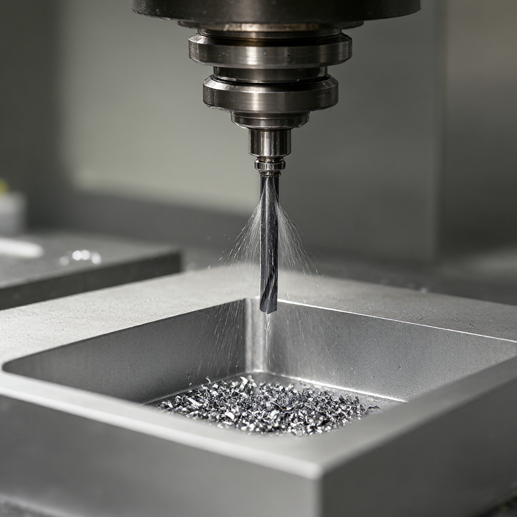
Typical Failure Mode of Chip Retention in Deep Cavity
The three most common types of failure in deep cavity machining are due to chip retention:
- Repeat cutting (Chatter Marking):Chip stuck in the bottom or side wall, the second contact occurs when the tool passes again, resulting in ripples or micro-chipping, especially in 5-axis milling complex surfaces are more easily ignored.
- Thermal deformation and size drift:Chip accumulation forms local insulation layer, heat sink effect causes softening of bottom material, size exceeds ±0.01mm tolerance zone; oxidation spots will be formed if there are uncleaned microchips before anodizing aluminum parts.
- Abnormal tool wear and tool breakage:Chips wrap around the main edge of the end mill or the end face of the ball cutter, and the sudden increase of cutting force causes the edge to collapse.
These failures amplify cosmetic defects in mass production-and high gloss and scratch free are key indicators of customer acceptance. Therefore, chip management is not only "clean", but also a pre-control link for accuracy and appearance consistency.
Effects of Cutting Parameters and Tool Geometry on Chip Ejection
The Relationship between the Speed, Feed and Chip Shape
Chip morphology is determined by chip thickness and curl radius. Common parameter combinations for deep cavity parts are as follows (6061-T6 aluminum, 8mm diameter micro end mill as an example):
| parameter | recommended value | Effect on chip discharge |
|---|---|---|
| speed of mainshaft | 8000–12000 rpm | High speed → thin chips and small curl radius → easy to stick tool; too low → thick chips and straight → easy to block cavity |
| feed per tooth | 0.03–0.05 mm/tooth | Feed is too low → Chip is not broken → Winding tool; Too high → Cutting force suddenly increases → Chip removal channel is deformed by pressure |
| lateral penetration | ≤0.2D | Full width and deep cavity roughing, lateral cutting → chip width and length → need to be smaller feed or sub-processing |
In engineering practice, deep cavity roughening stage often uses "layered Z cut"(Z-step 0.1 - 0.2D), each layer is completed with high-speed internal cooling nozzle purging, to avoid chip stacking.
Tool Geometry and Chip Removal Design
- Flute Geometry:3-edge micro-end mill chip removal groove shallow, suitable for finishing but chip removal efficiency is low;4-edge cutter in deep cavity roughing due to lack of chip space easy to block, it is recommended to use 3-edge, edge angle 90° micro-milling cutter, and increase the edge surface polishing to reduce the sticking chip coefficient.
- Tool aspect ratio:L/D>10 deep cavity tool rigidity is poor, chips are easy to adhere to the bottom under gravity and fluid drag. At this time, it is necessary to cooperate with internal cooling to spray the cutting fluid directly to the tip, chips are washed away from the cutting zone, rather than relying on gravity to fall naturally.
- Drilling Chip Removal:Deep hole drill (L/D>12) must use a drill with high chip removal efficiency (such as spiral angle above 30°), otherwise the chips will form a "chip column" in the hole and it will be easy to break the tool. During machining, the chips will be discharged to the tail along the guide rail. It is necessary to monitor the chip accumulation thickness in the guide rail area to avoid clamping the workpiece.
Comparison of Three Mainstream Chip Removal Schemes
There is no single "optimal solution" for chip management of deep cavity parts. It needs to be selected according to L/D ratio, material, batch and appearance requirements. The following three common solutions are compared:
| scheme | applicable scenarios | merit | localization |
|---|---|---|---|
| External Air Blast | L/D < 6,开粗后清腔 | Simple equipment, low cost, no interference with tools | Deep cavity (L/D>8) air flow can not reach the bottom, chip residue rate is high; aluminum chips are easy to be blown away to pollute the peripheral machined surface |
| Internal Coolant | L/D 4 - 12, finishing | Chips are directly washed away from the tip, surface Ra can reach 0.4μm, no sticking chips | The tool needs to have an internal cooling channel, and the cost of the small diameter tool is high; the oil remains at the bottom of the deep cavity and needs to be cleaned subsequently. |
| Dry + High-Speed Air | Non-stick tool materials (steel, titanium), high finish requirements | No residual cutting fluid, no cleaning before anodization; chips are carried away by high-speed air flow, reducing secondary contact | Aluminum, magnesium and other light metals have serious chip adhesion, which is not applicable; the cutting zone temperature rises, and the tool life needs to be monitored. |
Our engineering experience is: aluminum deep cavity finishing preferred internal cooling scheme, steel high finish requirements for dry cutting + air circulation, roughing stage unified plus external blowing as the bottom. In batch production, three schemes can be mixed-roughing with external blowing, finishing cutting internal cooling or dry cutting, to ensure that the chip state of each process can be controlled.
Key points of process practice: collaborative design from tool path to cooling
Tool Path Strategy and Chip Flow Management
The direction of chip flow in the cavity is determined by the direction of the tool path. Deep cavity roughing is recommended to use "outside-in" spiral cutter, rather than reciprocating layer by layer, so that chips are pushed to the outer wall discharge area, rather than accumulation in the center.
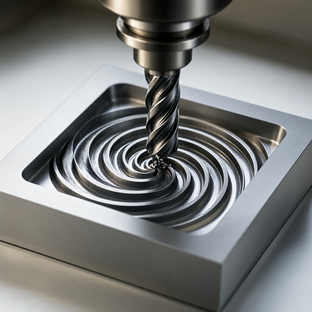
5-axis milling complex surface deep cavity, tool attitude angle (tilt) should be controlled at 15°-30°, avoid chips are "scraped" to the back of the tool. CAM software can be set up "chip flow prediction" module, simulation chip sliding track in the cavity, identify the detention area in advance.
Timing control of cooling and airflow
Chip evacuation is not "continuous blowing", but needs to match the cutting process timing:
- Open and thick interlayer:After each layer Z step is completed, pause the main shaft, purge with high speed air flow (0.6 - 0.8 MPa) for 3 - 5 seconds, and then cut the next layer.
- In finishing feed:Internal cooling is continuously turned on, and the air flow is only blown out briefly when the tool is withdrawn, so as to avoid the impact of air flow on the unsolidified surface.
- Before tool change/inspection:Forced external blowing + vacuum chip suction to ensure no chip interference during CMM (three coordinates) measurement and reliable size data.
This sequence needs to be written into the program during batch production to avoid batch differences caused by manual intervention by operators.
Inspection and Failure Avoidance: How to Check Chip Management Effectiveness
Whether chip management is in place, can not only rely on "visual chip free", need to be combined with quantitative inspection:
- Surface roughness:Deep cavity bottom Ra≤0.4μm (aluminum finishing), if Ra suddenly increased to 0.8μm above, indicating the existence of chip repeated cutting marks.
- size sampling:Tolerance of distance from bottom of deep cavity to side wall ±0.01mm, if individual parts in batch are out of tolerance, check whether chip accumulation thermal deformation occurs before finishing.
- Optical full inspection:100% full inspection of appearance before shipment, focusing on the inspection of micro-chip residue at the bottom of the deep cavity (using 50 times magnifying glass or AOI optical inspection), residual chips form oxidation spots after anodic oxidation, belonging to the appearance of Class I defects.
If batch chip problems are found, the retrospective order is: tool wear record → cooling pressure log →CAM tool path version → material lot (aluminum inclusions affect chip morphology). In most cases, the first two items are root causes.
Frequently Asked Questions (FAQ)
When CNC machining deep cavity parts, how much is the internal cooling pressure appropriate?
Usually 0.4 - 0.6 MPa can flush the chips away from the tip, too high pressure will blow away the cooled trace metal dust when withdrawing, polluting the surrounding surface. Aluminum finishing recommended 0.5 MPa start, according to the chip color (silver white is better, black is sticky) fine adjustment.
Can you omit external blowing and cut a layer directly at the opening stage?
Not recommended. Omitting inter-layer purging will lead to chip stacking 2 - 3 layers, the next layer of cutting chips are pressed into the material gap, the surface appears "extrusion", finishing need to increase the margin or use a smaller depth of cut to remove, but reduce efficiency.
How to deal with the chip stuck guide rail when machining the deep cavity of slender shaft by machine?
Chip accumulation in the guide area is a common failure of the centering machine. Preventive measures: when the chips are discharged along the tail end, increase the air flow assistance (0.3 MPa) on the guide side, and shorten the chip length (reduce the feed, increase the speed to make the chips curl). If it is stuck, stop the machine for manual cleaning, and set the chip monitoring sensor for early warning in batch production.
Is the dry-cutting scheme suitable for all metal deep cavity parts?
Not applicable. Aluminum, magnesium and other light metals have high chip sticking coefficient, chips are easy to wrap around the tool during dry cutting, and the risk of tool breakage is high. Steel, titanium, Inconel and other hard materials have less chip sticking. Dry cutting + air circulation is a feasible solution, but it is necessary to monitor the tool temperature rise. The replacement cycle is shortened by about 30% compared with wet cutting.
How to prevent deep cavity chipping problems from the drawing stage?
DFM (manufacturability analysis), if L/D>10 deep cavity no process hole or chip groove, it is recommended to increase the process hole (diameter 2 - 3mm) or slope (≥1°), so that chips have a natural slide channel. At the same time, mark the roughness requirements of the surface where the key size is located, so as to facilitate the targeted adjustment of cooling strategy in the machining stage.
Conclusions and recommendations for action
Deep cavity chip management is the hidden threshold for precision and appearance consistency. Through cutting parameter optimization, tool geometry matching, cooling air flow timing control and quantitative inspection, the lot defect rate caused by chip retention can be reduced to acceptable levels. If you are facing chip problems in deep cavity machining, send drawings and process requirements, and our engineering team will provide DFM advice, tool selection and cooling strategy solutions to support 15 - 25 day lot delivery.



