





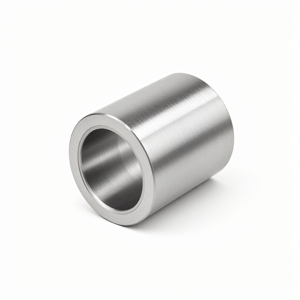
CNC machining pipe inner hole finishing core challenges and process paths
CNC machining of tubular parts in precision machinery, fluid control and structural supportbore finishingIt is often a key link that determines product function and life. Compared with cylindrical cutting, inner hole machining is limited by tool rigidity, chip removal space and measurement accessibility, and is prone to tool runout, thermal deformation and surface chatter. For engineers and purchasers, understanding how to break through these physical limitations and ensure that the inner hole size accuracy is controlled within ±0.01mm and the surface roughness reaches Ra0.4μm is the core yardstick for evaluating the technical strength of suppliers. Based on practical production experience, this article analyzes the internal hole machining strategy, tool selection logic and quality control points under different pipe diameters to help you avoid common failure modes at the beginning of the project.
Why is it harder to process inner holes than outer circles? Analysis of three physical limitations
Hole cutting is not a simple "reverse turning", and its process difficulties are concentrated in the following three dimensions:
- tool stiffness decay: The bending rigidity of the slender inner hole cutter decreases with the cubic degree of the overhang. When machining deep holes with a diameter of less than Φ10mm, small vibration can lead to the enlargement of the hole diameter or the generation of reticulation.
- Chip removal and chip accumulation: Closed cavity space limits the free flow of chips. If the chips are wrapped around the tool or hole wall, it is easy to cause secondary cutting, or even tool damage workpiece or tool.
- measurement blind zone: The outer circle can be quickly re-measured by micrometer, but the inner size of deep inner hole is difficult to obtain in real time. Usually, it depends on the process control after the first piece inspection. Once the preceding process is deformed, the subsequent finishing will fail.
Therefore, bore finishing is not only a programming problem, but alsoTool Geometry Parameters, Cutting Parameters and Fixture Rigiditysystem matching problem.
Machining strategy and equipment selection of pipe diameter segmentation
Depending on the ratio of pipe OD to ID (depth-to-diameter ratio), the machining strategy needs to be significantly adjusted. The following table compares the recommended routings for three typical pipe parts:
| part feature | typical inner diameter | recommendation device | critical process control point |
|---|---|---|---|
| Short pipe/flange | Φ5 - Φ30 mm | CNC turning/centering | Choose large clearance angle inner hole cutter, optimize feed ratio anti-vibration grain; clamping surface to ensure roundness. |
| medium length pipe | Φ10 - Φ50 mm | 3-axis/4-axis machining centers | Stepped drilling-rough boring-fine boring is adopted; attention shall be paid to the influence of drilling centering accuracy on the final aperture. |
| Deep hole/shaped pipe | Φ15 - Φ80 mm (depth-diameter ratio>5) | 5-axis linkage/special deep hole drill | Forced cooling lubrication, high-pressure cleaning chips; tools need to be equipped with grinding edge to compensate for yaw. |
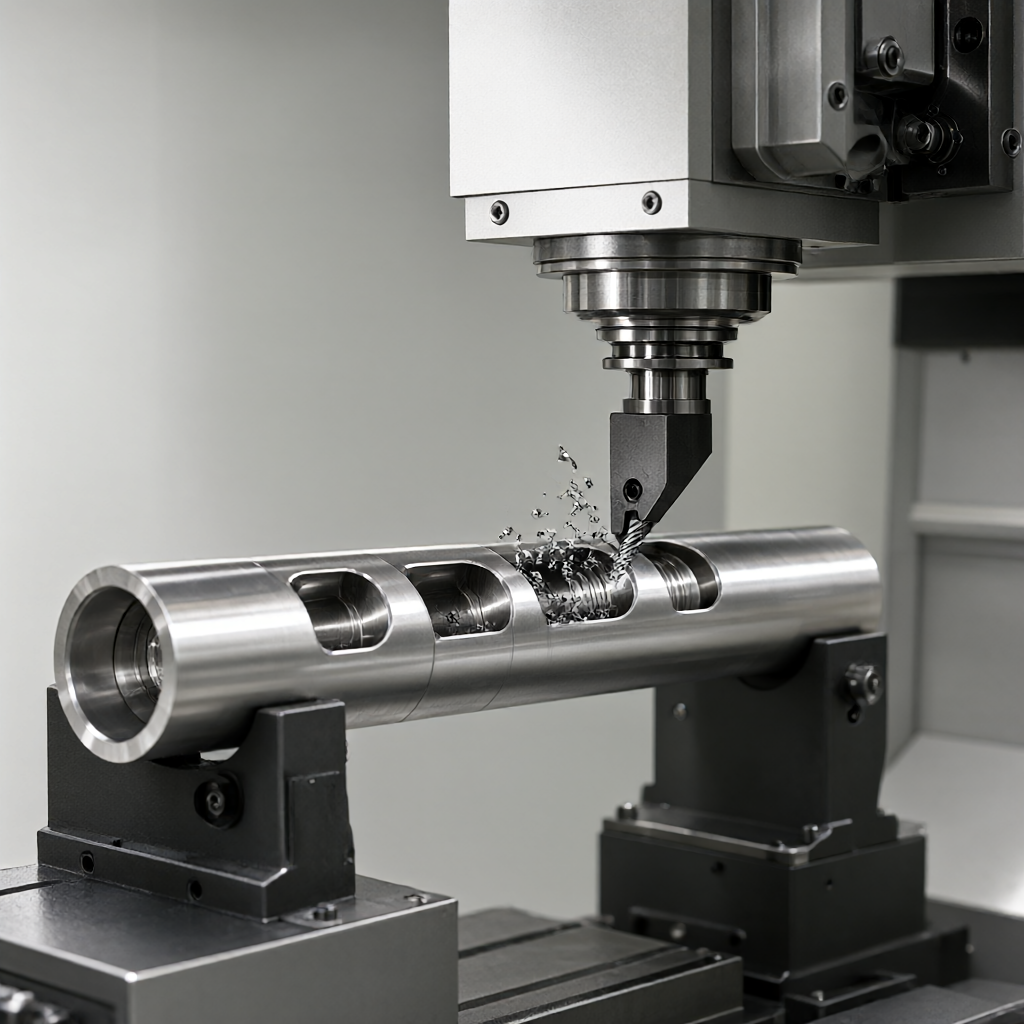
For pipe parts with complex inner cavity (such as axial thread and radial through hole),turning and milling compositeThe equipment has the advantage of completing internal and external processing in one clamping, which can significantly reduce the accumulated error of clamping and improve the concentricity.
Tool Selection and Cutting Parameter Optimization Guide
The geometric parameters of the inner hole tool directly determine the surface quality. In actual operation, it needs to be adjusted according to the material:
- principal declination selection: When machining thin-walled pipes or thin materials with large inner diameter, tools with main deviation angle of 90° or 95° should be selected to reduce radial cutting force and prevent tool deformation of pipes. When machining short and thick pipes, main deviation angle of 45° can be selected to enhance tip strength.
- Sharpening geometry: When finishing the inner hole, the cutting edge radius (Re) is usually 0.2-0.5mm. Re is too small and easy to break, too large increases radial resistance and reduces surface finish.
- cutting parameters: Take aluminum alloy as an example, the cutting depth can reach 1.0-1.5mm during rough boring, and the rotation speed can be 800- 1200rpm; 0.1-0.2mm margin is reserved during fine boring, and the rotation speed is increased to 1500- 2000rpm. The feed amount is controlled at 0.05-0.10mm/rev to ensure the roughness below Ra0.8μm.
For difficult cutting materials such as stainless steel, special coolant and high pressure internal cooling must be used to suppress the formation of work hardening layers and prolong tool life.
Surface Quality and Common Failure Mode Avoidance
In addition to size accuracy, appearance quality is another pain point for bore machining. Common failure modes and workarounds are as follows:
- ChatterThe root cause lies in the coincidence of the natural frequency of the process system and the cutting excitation frequency.avoidance scheme: Reduce the feed speed, increase the spindle speed, or modify the tool clearance angle.
- SpringbackWhen machining thin-walled stainless steel or titanium alloy, stress release after cutting material leads to hole rebound, resulting in measured size larger than theoretical value.avoidance scheme: Reserve elastic recovery allowance, usually calculate compensation value according to wall thickness, or gradually release stress through multi-cutter fine cutting.
- thermal deformationThe heat generated by continuous cutting causes the tool to thermally elongate and the aperture gradually increases.avoidance scheme: Use intermittent cutting to ensure that the coolant fully contacts the cutting edge, or use tools containing microcrystalline wax to reduce friction heat.
High-quality surfaces not only mean smooth, but also requireNo scratches, no flawsIn batch production, the uniformity of clamping force should be strictly controlled to avoid local indentation caused by soft jaw clamping.
Quality inspection and whole process control standard
Borehole detection is limited by depth and usually uses a combination of the following methods:
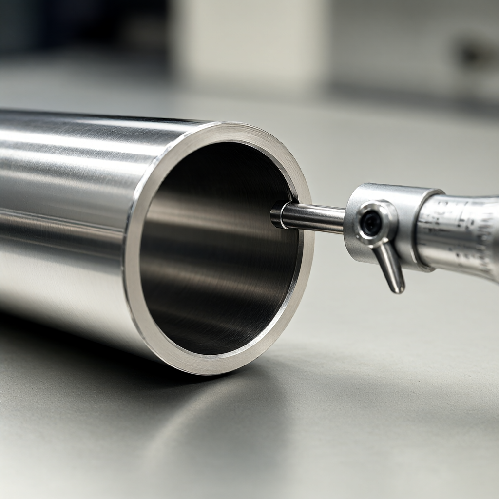
- first article confirmation: Pin gauge or pneumatic gauge is used to detect the diameter, and projector or profiler is used to detect the hole chamfer and surface roughness.
- process inspection: Sample hole diameter median and cylindricity every 5-10 pieces. If size drift is found, immediately trace spindle thermal error or tool wear.
- Full size shipment inspection: For critical mating surfaces, perform 100% full size inspection. Ensure bore coaxiality ≤0.02mm using CMM or special bore probes.
Before surface treatment (such as anodizing and electroplating), it must be confirmed that there is no residual chip and oil in the inner hole, otherwise it will lead to coating ablation or uneven oxide film thickness, affecting the final appearance consistency.
FAQ: Common questions about CNC bore finishing
How to ensure concentricity in deep hole machining?
The key lies in drilling centering. It is recommended to use a deep hole drill with a pilot bit for centering and then reaming. If the hole diameter is large, double head high horizontal support can be used, or the fourth/fifth axis rotation alignment can be used on the five-axis equipment to ensure that the inner and outer circles are coaxial within 0.05mm.
How to solve the problem of "aluminum tumor" after aluminum alloy inner hole processing?
Aluminum burl is usually caused by tool edge chipping or improper feed. It is necessary to replace a sharper cemented carbide coated tool, optimize the main deviation angle, and appropriately increase the speed and reduce the feed to ensure that the chips are continuously rolled out rather than squeezed on the hole wall.
Can you spray the bore directly after CNC machining?
Yes, but surface pretreatment (sandblasting or chemical polishing) is required to improve the roughness of adhesion. If the inner hole is a precision mating surface and size accuracy needs to be maintained, it is recommended to avoid spraying on the mating surface, or reserve a coating thickening allowance (usually 0.05-0.1mm).
Turning or milling for small batch pipe parts?
Depending on the thickness and length of the pipe wall. If it is a solid bar, choose turning; if it is a thick pipe or hollow profile, and the inner cavity is complex, choose machining center milling more flexible. The machine is suitable for mass production of small pipe shafts with large aspect ratio and high precision requirements.
How to evaluate the supplier's bore machining capability?
Check the equipment configuration (whether there is turning and milling compound or special deep hole equipment), tool library richness and detection means (whether there is pneumatic gauge or special inner diameter needle gauge). It is required to provide the first inspection report of the same type of pipe parts, focusing on checking the roundness and roughness data of the inner hole.
Conclusion and suggestions for cooperation
CNC machining of pipe inner hole finishing is a systems engineering, from tool selection to thermal deformation compensation, each step directly affects the final yield. We have 72 CNC equipment clusters, covering 3 - 5 axis and turn-milling composite process, supporting aluminum, steel, stainless steel and engineering plastics and other materials. In mass production, we emphasize the dual consistency of appearance quality and size accuracy to ensure smooth and flawless inner hole surface. If you have drawings or samples of pipe parts, welcomeSend Design Document Inquiry, we will provide you with detailed technical solutions and quotations including DFM recommendations.



