





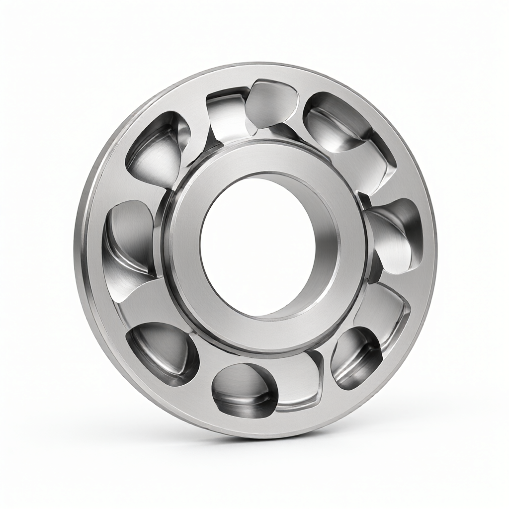
During the batch manufacturing of precision disc parts (such as flanges, couplers, bearing end caps),Surface Profile of CNC Machining Disc PartsIt is the core index that determines assembly tightness and bearing rigidity. Many engineers find that even if the tolerance is marked as 0.02 mm, the actual delivered parts still frequently appear "warpage" or local high points, resulting in poor end fit. This is not a simple lack of precision, but a combination of cutting deformation, thermal effects and clamping methods. This paper will analyze the surface profile machining principle in depth, provide practical operation parameters and acceptance schemes for aluminum, steel, stainless steel and engineering plastic disk parts, and help technical procurement and R & D personnel avoid common failure modes.
Surface profile failure mechanism: Why is disk parts difficult to flatten
Disk parts belong to typical thin-walled body of revolution, and its machining difficulty lies inradial stress reliefWhen rough or finish milling is performed, material removal can upset the original balance, causing the center of the workpiece to sink or the edge to rise. If the clamping force is too large, the thin-walled structure will elastically deform, and the rebound amount after tool withdrawal can often reach 0.05-0.1 mm, far exceeding the conventional tolerance. In addition, thermal deformation caused by tool wear and cutting heat can also accumulate in long-cycle machining, resulting in profile deviation of the first qualified middle part.
Quantitative effects of thermal deformation and stress release;
For aluminum alloy disks with a diameter of 200 mm, a linear thermal expansion difference of about 12 μm can be caused by a temperature difference of 5°C between the center and the edge. In the finishing stage, if coolant temperature control is not considered, the surface profile error is easily amplified. For materials with low thermal conductivity such as 304 stainless steel, cutting heat accumulation is more serious, and longer tempering stabilization time or segmented cooling process is needed to control deformation.
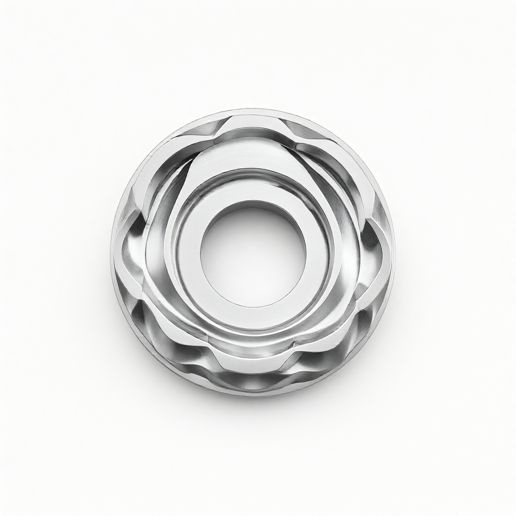
Comparison of clamping schemes: the first pass that determines the profile
The clamping method directly determines the deformation of the workpiece in the processing process. Disc parts usually use three-jaw chuck, special diaphragm chuck (Collet Chuck) or vacuum chuck. Different materials have great differences in clamping sensitivity. Choosing the right fixture is the premise of controlling ±0.01 mm accuracy.
| clamping method | Applicable materials/scenarios | Stiffness/deformation control | conversion efficiency | major limitation |
|---|---|---|---|---|
| Three-jaw pneumatic chuck | Thick wall steel parts, stainless steel | Medium (local clamping is easy to deform) | Low (to be corrected individually) | Thin-walled parts are easy to clamp out three-petal shape |
| Diaphragm chuck (Collet) | Thin-walled aluminum parts, high finish surface | High (360° evenly clamped) | High (integral replacement collar) | Limited diameter range, thin-walled, extremely light, still possible to shrink |
| Vacuum suction cup | Thin-walled aluminum sheets, composites | Very high (no mechanical stress) | High (fast adsorption) | Sealing surface required, heavy cutting and easy desorption |
| Spring Clamp | Porous disk, profiled parts | High (multi-point fit) | Medium (custom fixture required) | Higher cost, slight scratch risk to surfaces |
Engineering recommendations:For aluminum disks with Ra 0.4 μm high finish requirements, diaphragm chucks with soft jaws are preferred to control clamping deformation within 0.005 mm; for steel disks with complex cavities, multi-point multi-directional flexible jaws are recommended to avoid central depression caused by local stress concentration.
Cutting strategy and parameters: the key to separation of rough and fine processes
The core principle of controlling surface profile is"Coarse and fine separation, controllable margin". In rough machining, the cutting force should be reduced by the forward milling strategy, leaving a finishing allowance of 0.1-0.2 mm. In finishing, new tools must be used to avoid size drift caused by worn tools.
Example of aluminum finish milling parameters
- Material:6061-T6 aluminum alloy
- Cutters:φ10 mm end mill, coated carbide
- Speed:8000-10000 rpm (adjusted according to machine power)
- Feed rate:80-120 mm/min (light load finish milling)
- Depth of cut:0.05-0.1 mm (final feed)
- Cooling:High-pressure coolant injection keeps chips out instantly
Note:For 2 mm thick thin-walled aluminum plate, the fine milling depth should be reduced to 0.02-0.03 mm, and the feed rate should be appropriately reduced to 50-60 mm/min to prevent the tool effect from causing surface waviness. After processing, it is recommended to naturally warm up for more than 30 minutes, and then carry out size detection.
Machining Path and Tool Path Optimization
The surface profile of disk parts is sensitive to the continuity of the tool path. Sudden reversal or tool lift will produce tool marks, affecting the surface quality. Recommendedscrew downordiagonal cutFor large diameter disk parts, you can use the "zone milling" strategy, first milling 1/3 circumference of the outer ring, then milling the inner ring, and finally combining to balance the direction of thermal stress release.
Path logic to avoid the deformation of "clock face"
If the tool path causes the cutting force to always point to the center of the circle, the workpiece is prone to depression; if it deviates from the center of the circle, it is prone to bulge. Engineers should simulate the cutting force vector distribution when programming, and if necessary, usebevel milling, so that the direction of the main cutting force is evenly distributed on the circumference. Enabling the "forced down milling" function in the CAM software and setting the minimum cutting depth of 0.05 mm can effectively suppress such shape errors.
Inspection and Acceptance: From CMM to Optical Interference
The measurement of surface profile depends on the reference plane. If there is an error in the reference plane itself, the measurement result will be distorted. Acceptance criteria are usually referred toISO 1101 Definition of profile degree. For batch production, it is recommended to establish a multi-level inspection system:
- First Article Confirmation:CMM scans the whole size, generates point cloud data, and calculates the maximum profile deviation.
- Process inspection:Use high-precision marble platform + dial indicator to quickly screen obvious warpage parts, detection cycle 15-30 minutes/piece.
- Full inspection of shipment:For high finish parts, optical interferometer or laser flatness meter is used to detect the micro-undulations and macro-profiles of Ra 0.4 μm surface.
Key interpretation:If CMM data shows that the deviation of profile is concentrated in the range of 2 mm at the edge, it is mostly clamping deformation or thermal springback; if it is distributed in the whole section, it is mostly tool path or fixture stiffness problem. The inspection data should be recorded in the traceable file as the basis for process iteration.
Effect of Surface Treatment on Surface Profile
Many engineers ignore the contribution of surface treatment to the final size. Processes such as anodization and electroplating can change the surface size. For example, conventional anodization films are 10-15 μm thick and increase by about 5-8 μm on one side; electroless nickel plating films are 20-30 μm thick and increase by 10-15 μm on one side.
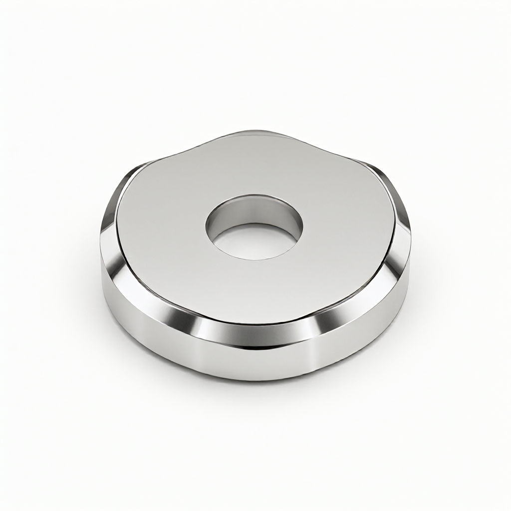
Engineering countermeasures:When CNC machining programming, it is necessary to reserve surface treatment allowance. If the customer requires a final surface profile of 0.02 mm and subsequent plating, the CNC machining size should be set according to (target value-film thickness ×2), and the coating uniformity error should be considered. For high finish mirror parts, electrolytic polishing is recommended instead of plating to reduce the impact on the surface microscopic geometry and maintain the mirror effect of Ra 0.2-0.4 μm.
FAQ: Frequently Asked Questions for Surface Profile Machining of Disk Parts
1. Thin-walled aluminum plate processing after the profile is too poor, how to adjust the process?
It is recommended to check the clamping deformation: use a diaphragm chuck or reduce the clamping force; reduce the finishing allowance to 0.02-0.03 mm; and then test it for more than 30 minutes after processing to eliminate the influence of thermal deformation.
2. Stainless steel plate surface network ripple, why?
Usually caused by tool harmonic resonance or spindle imbalance. Check tool dynamic balance, reduce feed rate by 10-20%, or change spindle speed beyond critical frequency, while ensuring sufficient tool rigidity.
3. How to improve the consistency of surface profile in batch production?
Implement first article validation and SPC process control. Regularly calibrate fixture zero with standard samples, monitor tool wear trends, establish tool life compensation tables, and ensure that each batch fluctuates within a controllable range.
4. Can engineering plastic plates also be made with high precision surface profile?
Yes. Plastic thermal deformation coefficient is large, need to be processed in low temperature environment, fast cutting to avoid local overheating. Select sharp carbide tools, small cutting depth high speed milling, can be effectively controlled within ±0.02 mm.
5. How to verify the supplier's surface profile detection ability?
Ask for CMM or optical interferometer inspection reports, view screenshots of point cloud data rather than single values. Ask for their reference plane selection logic and measurement uncertainty, and evaluate whether their inspection system supports ISO 1101 standards.
Conclusions and Recommendations for Action
The control of the surface profile of disk parts is a systematic project of clamping, cutting path, thermal management and inspection. By selecting the appropriate clamping method, optimizing finish milling parameters, reserving surface treatment allowance, and implementing hierarchical inspection, it can significantly Reduce form errors and ensure assembly performance. If you are looking for a CNC machining partner who can solve the problem of thin-walled disk warpage, has CMM inspection capabilities and supports small to high volume customization, please provide drawings and technical specifications, we can provide you with DFM advice and trial production quotation.



