





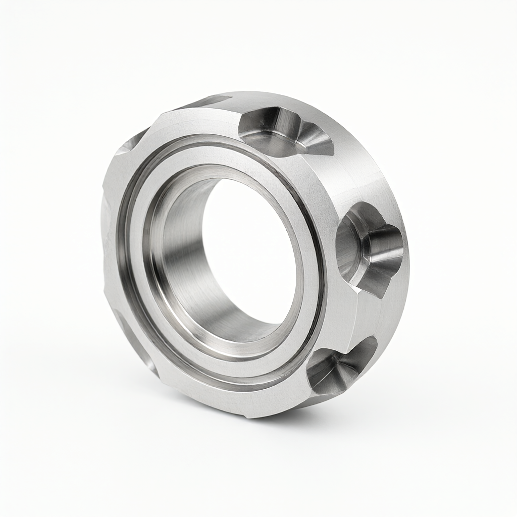
Core Challenges of Deformation Control in Stainless Steel CNC Machining
In the manufacturing of precision stainless steel components, dimensional drift and surface microcracks caused by residual stress release are the primary pain points faced by purchasers and engineers. Austenitic stainless steels (such as 304 and 316) have a high rate of work hardening and a low thermal conductivity (about 16-16.5 W/m·K). During the cutting process, frictional heat is difficult to dissipate rapidly, and a high-temperature concentration area is prone to form in the tool tip area, which can induce rapid tool wear and thermal deformation of the workpiece. For semiconductor equipment, medical implants or aerospace structural components with strict requirements for batch consistency, if there is a lack of effective deformation control strategies, it is very likely that failure modes such as flatness deviation and internal stress causing assembly jamming in the later stage will occur. Relying on a cluster of 72 CNC machines and combining 3-axis to 5-axis multi-faceted processing capabilities, ShowyMetal optimizes cutting parameters and clamping processes to stably control the dimensional accuracy of stainless steel parts within ±0.01mm, and the surface finish can reach Ra0.4μm. Ensure geometric stability and appearance quality during batch delivery.
In-depth Analysis of Material Properties and Cutting Mechanisms
The cutting performance of different grades of stainless steel varies significantly, which directly determines the selection of the process route. Austenitic steel (304/316) has extremely high toughness, large cutting force and is prone to sticking to the tool. Martensitic steel (420/17-4PH) has high hardness and strong wear resistance, but is sensitive to impact. Ferritic steel (430) has better thermal conductivity than austenitic steel and is relatively less difficult to process. The following table compares the key physical properties of three mainstream stainless steels in CNC milling and their impact on tool life.
| Material grade | Thermal conductivity (W/m·K) | Cutting hardening sensitivity | Typical failure risk | Recommended tool materials |
|---|---|---|---|---|
| SUS304 (A2) | 16.2 & | Extremely high (prone to sticking to knives) | Surface area dandruff tumor, size rebound | Coated cemented carbide/ceramic |
| SUS316L (CF8M) | 14.6 & | High (more resilient with molybdenum) | Tool chipping, thermal deformation | CBN knives/coated cemented carbide |
| SUS440C (17-4PH) | 9.8 & | Medium (high hardness) | Rounded corners and chipped edges of the blade tip | Diamond (soft state)/hard alloy |
From the perspective of cutting mechanism, stainless steel processing falls into the category of "difficult to cut". Its shear Angle is small and the deformation coefficient is large, resulting in short and curly chips and a long heat dissipation path. If the feed rate is too high, the chip friction will be intense, and the temperature at the tool tip can rapidly exceed 800℃, accelerating the oxidation and peeling of the coating. If the cutting depth is too shallow (<0.5mm), the tool will slide on the machined surface, creating a "plough effect", which instead intensifies the surface hardening layer and increases the difficulty of subsequent assembly. Therefore, avoiding the combination of "shallow cutting depth" and "high feed" is the first line of defense for controlling deformation.
Key cutting parameter setting strategy
Reasonable cutting parameters are the core means to suppress thermal deformation and tool wear. Take the milling of 304 stainless steel as an example. During the rough machining stage, it is recommended to adopt the strategy of "large depth of cut and medium cutting speed" : rotational speed 1000-1500 rpm, feed rate 0.2-0.3 mm/rev, depth of cut 3-5 mm. This parameter combination can ensure that the chips are quickly removed and reduce the accumulation of frictional heat. During the finishing stage, "low depth of cut and high surface finish" are required: the rotational speed is increased to 1500-2000 rpm, the feed rate is reduced to 0.05-0.1 mm/rev, and the depth of cut is 0.2-0.5 mm, aiming to eliminate tool marks and control the residual height on the surface.
Selection and flow control of coolant
Water-soluble emulsified cutting fluid is the mainstream choice for steel part processing. However, for stainless steel, high-concentration emulsions containing extreme pressure additives (EP) (with a concentration of 8%-10%) must be used, and a stable flow rate (≥10 L/min) should be maintained. Although low-pressure jet cooling can lower the temperature, if it is not aimed at the tool tip, the cooling effect is minimal and it is prone to cause local rapid cooling of the workpiece, generating new residual stress. It is recommended to adopt "full submerged machining" or "micro-lubrication (MQL)" in combination with high-pressure internal cooling tools, ensuring that the cooling medium directly acts on the cutting edge, keeping the tool temperature below 500℃, and significantly extending the tool life to 1.5 to 2 times that of ordinary milling.
Fixture design and stress relief process
The clamping force directly determines the deformation amplitude of the workpiece during the processing. For thin-walled or deep-cavity parts, rigid fixtures may cause clamping deformation and excessive rebound after unloading. In the DFM recommendations, ShowyMetal usually recommends the use of "multi-point spring chucks" or "vacuum adsorption" solutions to disperse the single-point clamping force and reduce the risk of local indentation. In addition, the release of residual stress is a key link in deformation control. It is recommended to allow the parts to stand at room temperature for 1-2 hours after rough machining (natural stress relief), or to perform stress relief annealing at 600 ° C for 2 hours for high-value parts. For heat-treatable materials like 17-4PH, it is necessary to strictly control the heat treatment batches to ensure that the hardness fluctuation within the same furnace is ≤ HRC 1, avoiding dimensional drift caused by the difference in cutting force due to uneven hardness.
The advantages of multi-axis linkage are highlighted here: by using 4-axis or 5-axis machining centers, multi-surface processing can be completed in a single clamping, avoiding the accumulation of secondary positioning errors. This is the key technical path to ensure the coaxiality and flatness of complex stainless steel parts. For slender shaft parts, the Swiss-type centerless machine, in combination with the tailstock support, can effectively suppress overhang vibration and keep the radial runout within 0.005mm.
Common Failure Modes and Avoidance Schemes
Although process optimization can significantly reduce risks, stainless steel processing still faces several typical failure modes that need to be specifically avoided:
- Adhered knife and built-up edge It is manifested as deterioration of surface roughness and unstable dimensions. Avoidance solution: Increase the rake Angle of the tool, select AlTiN or TiAlN coated tools, raise the cutting speed to over 200 m/min, and separate the cutting layer from the low-energy zone.
- Thermal deformation out of tolerance It is manifested as flatness deviation and hole position offset. Avoidance plan: Force the use of internally cooled tools, reduce idle travel time, and arrange finishing after the machine tool has reached thermal equilibrium (preheat for 30 minutes after startup).
- Tool chipping It is manifested as white scratches and burrs on the surface. Avoidance plan: Avoid the combination of high feed and low cut depth, regularly check the integrity of the tool coating, and use inserts with chip breaking grooves.
In ShowyMetal's quality system, each stainless steel part must undergo full-size inspection with a three-coordinate measuring machine (CMM) and random inspection with a surface roughness meter before shipment to ensure that the Ra value meets the drawing requirements (usually ≤0.8μm, critical surfaces ≤0.4μm). For appearance-sensitive parts, we add additional sandblasting or brushing processes to eliminate cutting marks and enhance batch consistency.
Acceptance criteria and quality inspection procedures
The quality of the final delivery depends on the rigor of the inspection process. The acceptance of stainless steel parts usually follows the following levels:
- Dimensional accuracy The tolerance of key mating surfaces should be controlled within ±0.01mm, and that of non-key surfaces within ±0.05mm. A full inspection should be carried out using a CMM or pneumatic measuring instrument.
- Surface quality Roughness: Ra0.4-0.8μm, no scratches, no corrosion spots (salt spray test ≥ 48 hours no red rust).
- Mechanical properties When necessary, conduct random hardness checks (Rockwell HRC 30-34 for 304/316 solution state) to ensure the correct heat treatment condition.
We have established four lines of defense: "incoming material inspection → first article confirmation → process inspection → full inspection before shipment". During the first piece confirmation, the process engineer needs to review the tool wear curve and the size trend chart. If the size drift rate exceeds 0.005mm/10pcs, the tool replacement and parameter adjustment process should be immediately triggered to prevent batch scrapping.
FAQ: Q&A on Stainless Steel CNC Machining Technology
What is the tool life when CNC machining 304 stainless steel?
Under reasonable parameters (vc=200-300 m/min, f=0.1-0.15 mm/rev) and internal cooling conditions, the service life of coated carbide end mills is usually 5-8 hours or capable of processing 200-300 pieces, depending on the depth of cut and material hardness.
How to prevent deformation of thin-walled stainless steel parts during processing?
It is recommended to adopt a coarse and fine separation strategy and carry out stress relief processes before fine processing. The fixture uses multi-point soft claws or spring chucks to disperse force. The finishing allowance should be controlled at 0.1-0.2mm to avoid plastic deformation caused by large cutting force.
Is 316L more difficult to process than 304? What are the differences in parameters?
316L, due to its molybdenum content, has higher toughness and is more likely to stick to the knife. It is recommended to reduce the feed to 0.08-0.1 mm/rev, increase the rotational speed by 10%-15%, and force the use of high-pressure internal cooling tools to remove chips and cool down.
What pretreatment should be done before surface treatment of stainless steel parts?
Thorough degreasing and oil removal (ultrasonic cleaning) are required to eliminate residual cutting fluid and prevent pitting and color differences during anodizing or electroplating. The rough-machined surfaces need to be deburred to prevent the accumulation of processing fluid.
How long is the general delivery time for mass-produced stainless steel parts?
ShowyMetal bulk orders are usually delivered within 15 to 25 days, depending on the complexity of the drawings and surface treatment requirements. The sample-making cycle is relatively short and can be scheduled in accordance with project milestones, depending on the current production capacity load.
Conclusions and Cooperation Suggestions
Stainless steel CNC machining is not merely about "cutting metal", but a systematic project involving materials science, thermodynamics and mechanics. Effective deformation control relies on the precise setting of cutting parameters, the rigid balance of fixtures, and a rigorous stress release process. Selecting a manufacturer with a 72-unit equipment cluster, familiar with the properties of multiple materials, and having a complete quality inspection system is the key to reducing project risks and ensuring batch consistency. If you have processing requirements for stainless steel structural components, shaft parts or complex polyhedral parts, please feel free to send us your drawings and process requirements. We will provide you with DFM suggestions and detailed quotation plans.



