





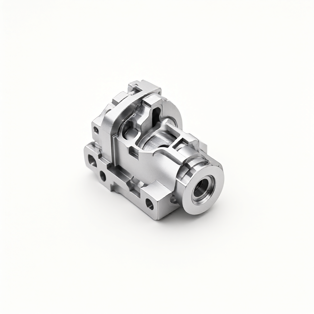
Precision Fit CNC parts Design: Analysis of Machining Stability for H7 Tolerance Grades
In precision mechanical assembly, the H7 tolerance grade is the core standard for ensuring the consistency of the fit between holes and shafts. For engineers and purchasers engaged in the design of precision fit CNC parts, understanding the impact of H7 on processing stability is the key to controlling the rework rate and reducing the risk of assembly interference. H7 is not a single value but a tolerance zone that varies with the basic dimensions. Its upper limit is usually 0 and the lower limit is negative (for example, the tolerance of φ50 H7 is +0.000/ -0.025mm, that is, the size range is 49.975- 50.000mm). This single-sided negative deviation characteristic requires CNC machining to have extremely high dimensional center positioning capability and process control ability. Even a slight offset can lead to interference or insufficient clearance.Understand the engineering meaning and design constraints of the H7 tolerance zone.
The tolerance value of H7 varies step by step with the diameter.
H7 belongs to IT7 grade fit, and its tolerance value T increases with the increase of the basic size. Take common bushings as an example:- φ10 H7 : + 0.015/0 (size 10.000-10.015)
- φ30 H7 : + 0.021/0 (dimensions 29.979-30.000)
- φ80 H7 + 0.030/0 (size 79) 970-80.000)
The key impact on DFM (Design for Manufacturing)
The ratio of hole depth to diameter (L/D) limits the machining stability.
When the hole depth exceeds 3 to 4 times the diameter, drilling and reaming compound processing is prone to tool deflection, thermal deformation and tool vibration, causing the size to shift towards the lower limit of the tolerance zone. It is recommended that the "drilling - reaming - precision boring" process be adopted when L/D ≤ 3. L At 3, it is necessary to assess whether to switch to deep hole drilling or electrical discharge grinding, or mark "process according to the upper deviation" on the process card and cooperate with online measurement compensation.Comparison of Core Process Paths for CNC Machining of H7 Holes
Option One: Drilling - Reaming - Finishing boring (applicable to L/D ≤ 3)
This path has a relatively low cost and is suitable for mass production. Leave a allowance of 0.5-1.0 mm for rough drilling, reaming to H8, and finish boring to H7. Critical Control points- Tool rigidity The diameter of the precision boring tool bar is ≥ 0.6 times the hole diameter, reducing the overhang ratio.
- Cutting parameters The feed rate for fine boring is 0.05-0.10 mm/rev, the cutting depth is 0.05-0.10 mm, and the spindle speed is set at Vc = 60-80 m/min (for hard alloy boring tools).
- "Benchmark unification" Reaming and precision boring are coaxially positioned to avoid secondary clamping errors (usually ≤ 0.005mm).
Option Two: Rough Boring - Fine Boring (applicable to L/D 1-4, high surface finish requirements)
Skip the drilling process and directly perform rough boring with a allowance of 0.8- 1.5mm, and then perform fine boring to the required size. The advantages are that the surface roughness is more likely to reach Ra 0.8-0.4 μm, and the porosity is good. The disadvantages are that the cost of cutting tools is relatively high and there is a higher requirement for the thermal stability of machine tools.Option Three: Electrical discharge grinding/grinding (applicable to high-hardness materials or L4)
For hardened steel (HRC 50-58) or deep holes, the final processing is carried out by electrical discharge machining or internal cylindrical grinding after CNC boring. It can ensure the H7 size and avoid thermal deformation, but the cycle is long and the cost is high. It is suitable for small-batch high-value parts.Comparison Table of H7 Stability in Different Processing Schemes
| Process path | Applicable to L/D | Dimensional stability (batch Cpk) | Surface roughness Ra | Unit cost (relative) | Typical failure modes |
|---|---|---|---|---|---|
| Drilling - reaming - finishing boring | ≤ 3 | Cpk ≥ 1.33 (after stabilization) | Ra 0.8-1. 6 μm | Low | Make the size of the knife too small; Center deviation |
| Rough boring - Finish boring | 1-4 | Cpk ≥ 1.67 | Ra 0.4-0.8 μm | "Chinese" | Dimensional drift caused by thermal deformation; Sudden tool wear |
| Electrical discharge/grinding | > 4 or high hardness | Cpk ≥ 2.0 (final processing) | Ra 0.2-0.4 μm | "High | Uneven discharge gap of EDM; Grinding burns |
Five Process variables Affecting H7 Batch Consistency
1. Thermal drift of machine tools
When processing the first piece, the CNC spindle and the bed are heated by 2 to 5°C, resulting in a reduction of the hole size by 0.005 to 0.015mm. Avoidance solution: After turning on the machine, execute the "warm-up program" (idle run for 20 to 30 minutes); Or after the first piece is confirmed, dynamically adjust the offset value in the G code (such as 40-49 offset) according to the thermal compensation table.2. Tool wear and compensation lag
For every 0.01mm of boring tool wear, the hole diameter increases by 0.01mm. If not ground in time, the H7 hole will exceed the upper limit. It is recommended to trigger an online measurement (using an internal micrometer or pneumatic measuring instrument) every 30 to 50 pieces processed, and enable the tool life management function, which will automatically alarm when wear exceeds the limit.3. Clamping deformation and stress release
For thin-walled parts (wall thickness ≤ 3mm), the ellipticity of the hole can reach 0.01- 0.03mm after compression, and the rebound after release causes dimensional deviation. Countermeasures: Adopt vacuum adsorption or soft claw low-stress clamping; Or reserve a 0.05mm elastic recovery allowance before fine boring and let it stand for 30 minutes before measurement.4. Batch differences of materials
The cutting plasticity of aluminum alloys (such as 6061-T6) and stainless steel (304) is different. Even when processed with the same parameters, the dimensional center may drift by 0.008mm. Incoming material inspection requires checking the heat treatment status and recalibrating the feed compensation value on the first piece.5. Measurement system and three-coordinate programming error
The tolerance zone of H7 is only 0.021mm (φ30), and the error of the CMM probe (usually 0.003-0.005mm) accounts for 15-25%. Polyhedral probe compensation should be adopted, and it is necessary to ensure that the measurement procedure includes a "contact stability" delay. It is recommended that 100% full inspection be carried out on key components rather than random inspection.Acceptance criteria and requirements for test reports
Dimensional and positional tolerances
The acceptance of H7 holes is not only based on the diameter but also requires inspection:- Cylindricity ≤ 0.01mm (ensure uniform contact of the mating surfaces)
- Coaxiality ≤ 0.02mm (if forming a bearing housing with the outer circle)
- Positional degree According to the drawing marking, usually ≤ 0.05mm



