





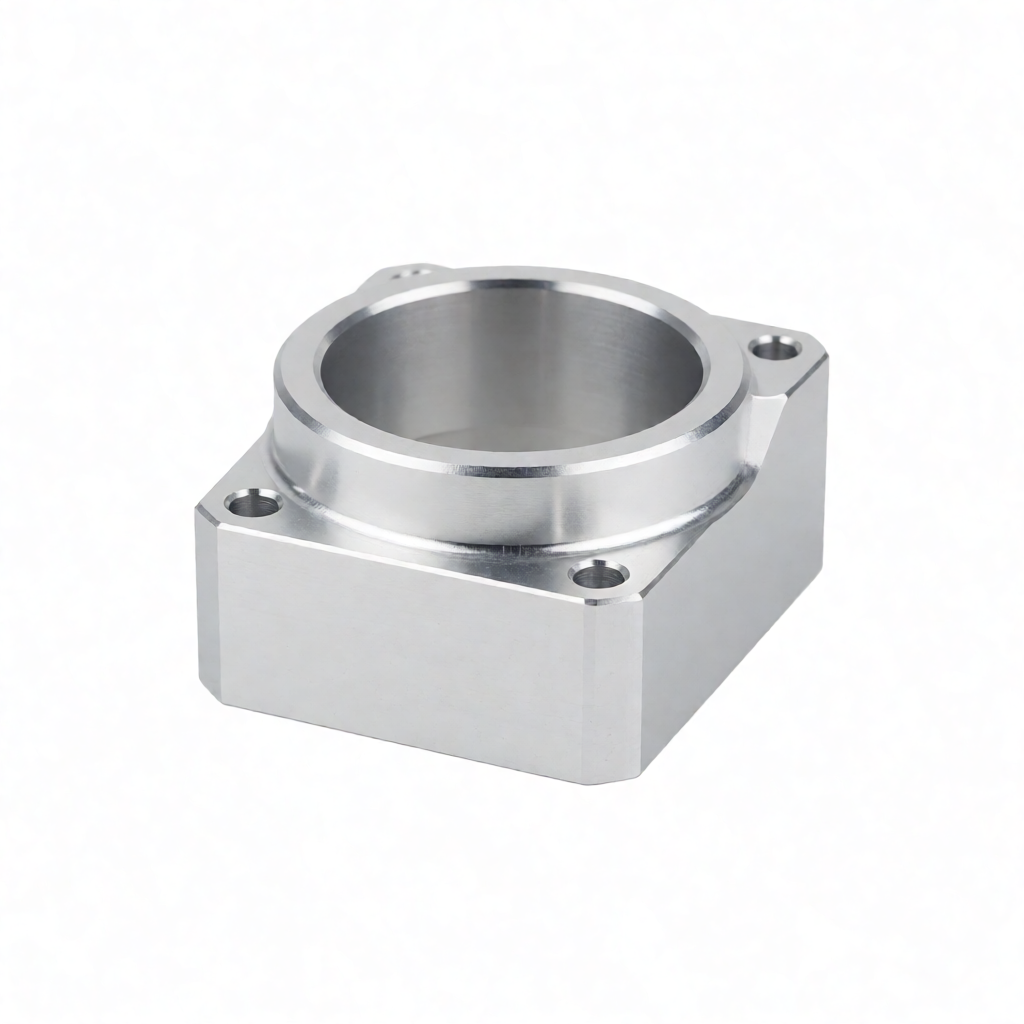
Analysis of Tolerance and Surface Integrity of Robot Joint Mating Surfaces in CNC Parts Design
In the design of robot joints, the dimensional stability and surface integrity of the mating surfaces directly determine the Backlash (Backlash) and long-term motion accuracy after assembly. This article focuses on... strong> CNC parts Design The key engineering decisions at this stage provide practical tolerance allocation, cutting parameter optimization and surface roughness control strategies for the shaft-hole fit, flange interface and sealing surface of the robot joint, helping the R&D and procurement teams avoid common assembly interference and wear failure during the DFM stage.
Engineering Requirements and Failure Modes of Robot Joint Mating Surfaces
The core function of robot joints (such as rotary joints and linear modules) is to transmit torque and maintain positioning accuracy. The mating surfaces usually include: bearing mounting seats, shaft pin holes, flange positioning stop mouths and sealing surfaces. These parts are subjected to periodic loads, which are subject to the impact of... strong> Shape tolerance And Coaxiality Extremely sensitive.
- Excessive backlash: Inaccurate positioning is usually caused by excessive bore diameter deviation, small shaft diameter or improper fit clearance.
- Assembly interference: The roundness of the stop or the dimensional deviation of the step depth can cause the bearing to get stuck or require forced press-fitting.
- Early wear: Excessive surface roughness Ra causes microscopic peak-valley friction, leading to the rupture of the lubricating oil film and accelerating pitting corrosion.
- Stress concentration: Improper chamfering radius or residual tool marks from processing can lead to the initiation of fatigue cracks.
During the design stage, the functional boundaries must be clearly defined: for instance, for high-response servo joints, the coaxiality is typically controlled within 0.02mm. The surface roughness Ra is recommended to be ≤ 0.8 μm, and it can reach Ra 0.4 μm under high finish requirements.
Tolerance allocation strategy for key mating surfaces
The accuracy of the mating surfaces depends on the selection of the "fit system" and the "tolerance grade". The common base hole system (H7/h6 or H7/k6) or base axis system for robot joints should be determined based on the interchangeability requirements.
Selection of shaft-hole fit tolerance
For the bearing positions of precision joints, it is recommended to use IT6 or IT7 grade . For example, a bearing hole of φ 30mm:
- Clearance fit (H7/g6) : It is used in situations where light pressing is required and there is relative movement, with a maximum gap of approximately 0.027mm.
- Interference fit (H7/k6) : It is used to bear heavy loads and prevent shaft rotation, with a minimum interference fit of approximately 0.005mm and a maximum of 0.023mm.
Design highlights: In the DFM review, it is advisable to avoid choosing wide tolerance grades of H8 and above for critical transmission surfaces; otherwise, the consistency risk in mass production is extremely high. If the structure of the part permits, "grinding finishing" can be adopted instead of "finishing" to ensure dimensional stability.
Shape and position tolerance (GD&T) marking
Merely marking dimensional tolerances is insufficient to control assembly quality. Form and position tolerance constraints must be added:
- Coaxiality: It is recommended that the reference surfaces of the inner and outer rings of the bearing be marked with 0.02mm.
- Roundness: It is recommended to mark 0.01mm on the cylindrical surface to prevent local stress concentration caused by "ellipticity".
- Flatness: The flange sealing surface is recommended to be ≤ 0.03mm to ensure uniform contact of the sealing ring.
Processing technology selection: 3-axis milling vs. turning and milling compound.
The structural characteristics of different mating surfaces determine the optimal processing path. The following is a comparison of two mainstream process paths for reference in the DFM stage:
| Parameter item | 3-axis / 4-axis CNC milling | Turning and milling compound/through-spindle machine |
|---|---|---|
| Applicable features | Flange plates, polygonal brackets, complex side surfaces, non-rotating bodies | Shafts, sleeves, rotationally symmetrical mating surfaces, and shafts with a large slenderness ratio. |
| Coaxiality control | Relying on clamping accuracy, multiple clamping accumulate errors; Reference plane positioning is required. | One clamping can complete turning, milling and grinding, and the coaxiality can reach 0.005- 0.01mm |
| Surface roughness | Conventional Ra: 0.8-1.6 μm; Precision milling and polishing can reach Ra 0.4 μm<. | Conventional Ra: 0.4-0.8 μm; Precision turning and grinding can achieve Ra 0.2-0.4 μm<. |
| Efficiency and Cost | Multi-process transfer, with a relatively long cycle; The equipment has strong versatility. | Single-station continuous processing, short cycle; Suitable for large-scale production and high-precision shafts. |
| Thermal deformation risk | Slight deformation caused by cutting heat requires tempering to relieve stress. | Optimization of processing paths, controllable heat accumulation; High-precision workshops require constant temperature. |
Selection suggestion: If the main body of the joint is a rotating body (such as a joint axis), it is strongly recommended to use Turning and milling compound Or "Zouxin" Process to ensure the coaxiality of the journal and the bearing position. If it is a flange connection plate, using 4/5-axis milling for one-time forming can avoid the reference conversion error caused by multiple clamping.
The influence of materials and heat treatment on mating surfaces
Material properties determine the stiffness and deformation tendency of parts, which in turn affect the final dimensional accuracy.
Selection of Common Alloy Steels
- 40Cr / 42CrMo: After quenching and tempering treatment, the hardness is HRC 28-32, and it has excellent comprehensive mechanical properties. Suitable for medium-load joints. The deformation during heat treatment is usually controlled within 0.05mm, and a grinding allowance of 0.1- 0.2mm should be reserved.
- 17-4PH (Precipitation Hardened Stainless) : High-strength stainless steel, corrosion-resistant. After hardening treatment (H1100), the hardness is HRC 30-40, with minimal deformation, making it suitable for outdoor robots that are sensitive to rust.
- 7075-T6 Aluminum: Lightweight application. Its strength is lower than that of steel, but it is commonly used in situations where weight reduction is required. It is necessary to pay attention to the "tool deflection" phenomenon of aluminum parts during cutting, and the cutting parameters should be conservative.
Residual stress elimination in heat treatment
If there are residual stresses on the mating surfaces, they will be slowly released during service, causing dimensional "drift". It is recommended to carry out the process after processing is completed and before fine grinding. strong> Stress relief annealing Or Aging treatment . For instance, after quenching and tempering 42CrMo, it is recommended to let it stand for 24 to 48 hours to stabilize before fine processing, or use low-temperature aging to release stress. This step is crucial for ensuring a dimensional accuracy of ± 0.01mm.
Surface integrity and finish control
Surface roughness (Ra) not only affects appearance but is also directly related to the coefficient of friction and fatigue life.
Correlation between roughness index and processing parameters
- Ra 1.6 μm (rough machining) : The rough cutting depth ap is 2-3 mm, and the feed f is 0.3-0.5 mm/r. At this point, the knife marks are obvious and are not suitable for the mating surfaces.
- Ra 0.8 μm (semi-finished) : The finish turning/finish milling allowance is 0.1-0.2 mm, and the feed f=0.05-0.1 mm/r. Most industrial joints can accept this grade.
- Ra 0.4 μm (finishing) : The margin should be no more than 0.05mm, and the feed f=0.02- 0.03mm /r. Sharp blades should be used and the coolant should be optimized. Suitable for high-precision guiding surfaces.
- Ra 0.2 μm (mirror finish/ground finish) : It usually needs to be combined with honing or polishing processes. It is used for extremely demanding parts such as the main shaft journal.
Process details to avoid processing defects
In mass production, Appearance consistency It's a pain point. To avoid scratches and flaws, it is recommended to use dedicated finishing tools in the final process and isolate the transportation links. For anodized or electroplated parts, the mating surfaces need to be treated. strong> Sealing treatment Or Shielding protection Prevent the thickening of the oxide film from causing a reduction in the fit clearance. For instance, the thickness of the anodic oxide film is typically 10-20 μm, and this thickness needs to be considered in both directions when designing the gap.
Inspection methods and acceptance criteria
The acceptance of mating surfaces cannot rely solely on "visual inspection", but must be combined with quantitative detection. The following test combinations are recommended:
Dimensional and positional tolerance inspection
- Coordinate measuring Machine (CMM) : Check the reference surface, stop mouth and coaxiality. The accuracy can reach 0.001mm. It is recommended that all key batches undergo 100% full inspection.
- Optical projection microscope: Rapid detection of chamfers, roundness and surface cracks. It is more efficient than CMM and suitable for online inspection.
- Roughness meter: The Ra value was detected in accordance with the ISO 4287 standard. Note that the probe direction should be perpendicular to the processing texture direction, and take the average value of three points.
Assembly verification (before PPAP)
It is recommended to perform it before mass production. strong> "Simulated assembly test . Pre-assemble the processed joint shafts and bearings, and measure the rotational resistance (Torque) and Axial Play (Axial Play). If the backlash exceeds the specification (e.g. 0.1mm), the processing parameters should be traced back to check for tool wear or clamping runout.
Frequently Asked Questions FAQ
What is the general requirement for the coaxiality of robot joint axes?
Generally, the coaxiality of the key drive shaft is recommended to be within ± ±. strong> 0.02mm Within this, the high-precision servo joint can reach 0.01mm. The specific values need to be inferred based on the Backlash specification (Backlash Spec) of the joint. It is recommended to confirm the preload fit tolerance with the bearing supplier.
Can a surface roughness of Ra 0.4 μm be directly achieved through 3-axis milling?
Sure, but it's quite difficult. Small feed (≤ 0.02mm /r), sharp inserts and optimized spindle speed should be used during the finish milling stage. If extremely high reliability is required, it is recommended to add it after milling. strong> Fine grinding Or Honing The process is to remove the milling tool marks and ensure dimensional stability.
3. Will the fit clearance become smaller after anodizing? How to reserve?
Yes. The thickness of the anodic oxide film is usually 10-20 μm, covering the shaft and holes, and the actual gap is reduced by 20-40 μm. When designing, it should be based on theoretical gaps. strong> Increase by 0.04-0.05 mm The compensation value, or Masking on the mating surface without oxidation, only oxidizes the non-mating area.
4. How can we ensure that there are no scratches on the appearance during mass production?
Adopt Individual packaging (Blister boxes or foam gaskets), to prevent metal contact between parts; Regularly sharpen the processing tools. When loading and unloading workpieces, use soft chucks or pneumatic suction cups. "Establish First Article Inspection The system focuses on inspecting the smoothness and consistency of the appearance.
How to control the dimensional deformation of 5.42CrMo after heat treatment?
The key lies in Reserved grinding allowance . Usually, a single-sided allowance of 0.1 to 0.15 mm is reserved for each mating surface. After heat treatment, grinding and finishing are carried out. In addition, the loading method (vertical/horizontal) of the heat treatment furnace and the cooling rate also affect deformation. It is recommended to select a precision heat treatment plant with good constant temperature control and conduct batch stability tests.
Conclusions and Next Steps
The design of the mating surfaces of robot joints is a systematic project, involving the coordination of tolerance allocation, material heat treatment, processing technology and surface treatment. Through Turning and milling compound Or High-precision grinding Control coaxiality through Strict roughness management Reduce wear and tear, and then through CMM Full inspection Ensuring batch consistency is the key path to enhancing reliability.
If you are designing a new generation of robot joints or are facing problems such as excessive backlash and surface wear of existing parts, we welcome you to provide 2D/3D drawings and material specifications. Our engineering team can assist with DFM reviews, provide tolerance optimization suggestions and processing technology solutions (including 3/4/5-axis milling, turning and milling compound, grinding, etc.), and support your mass production requirements with ± 0.01mm accuracy and Ra 0.4 μm surface quality. Send the drawings and you can get detailed process descriptions and estimated delivery dates.



