





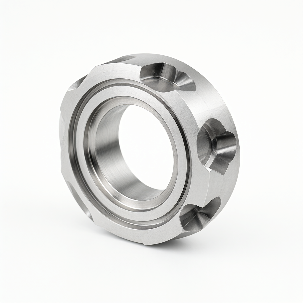
The design of high-tolerance hole avoidance in stainless steel is the core difficulty in the customization of precision CNC parts. For components made of stainless steel materials such as 304, 316L or 17-4PH, if engineers do not rationally plan the hole positions to avoid them during the drawing review stage, it is very likely to cause tool collision, hole wall deformation or residual processing stress, which will further affect the consistency of batch delivery. As a manufacturer specializing in custom precision CNC parts, ShowyMetal, drawing on the processing experience of 72 CNC machines, offers engineers DFM (Design for Manufacturability) suggestions for high-tolerance holes in stainless steel, helping you ensure ±0.01mm accuracy while optimizing appearance quality and production cycle.
The influence of stainless steel material Properties on Hole Design
Compared with ordinary carbon steel or aluminum alloy, stainless steel has significant differences in cutting performance, which directly restricts the design freedom of high-tolerance hole positions.
- Large cutting force and thermal effect Stainless steel (especially 316L) has good chip toughness and is not prone to chip breakage, which leads to rapid tool wear and high cutting heat. If the hole spacing is too close (usually less than twice the hole diameter), local heat accumulation will lead to uneven distribution of residual stress, causing micro-deformation of the parts.
- Work hardening tendency Austenitic stainless steel will harden rapidly on its surface during the cutting process, which increases the difficulty of subsequent fine machining. If the hole position avoidance design is improper and the allowance left during rough machining is too large, it is easy to cause tool deflection during finish machining.
- Stress relief annealing window For precipitation-hardening stainless steels such as 17-4PH, if the holes are concentrated in stress-sensitive areas, the annealing process needs to be evaluated. When designing, it is advisable to avoid placing key holes at corners where stress concentration is likely to occur.
Therefore, in the design of stainless steel parts, the avoidance of holes is not only a matter of spatial layout, but also a problem of thermal management and stress management. It is recommended that engineers introduce process analysis at the early stage of the CAD model to ensure that the hole distribution is conducive to chip removal and heat dissipation.
The core design principle of high-tolerance hole position avoidance
To achieve a tolerance of ±0.01mm or even more stringent, the hole position avoidance should follow the principle of "minimum cantilever and maximum support", while also taking into account the risk of interference in the tool path.
The relationship between the minimum center distance and the tool radius
When two high-tolerance holes are located in adjacent areas, the minimum material thickness (Ligament) between the hole walls is of crucial importance. For holes with a diameter of D, if a tolerance of ±0.01mm is required, it is recommended that the minimum center distance be no less than 1.5D to 2D. If it must be less than this value, drilling should be used instead of boring, or a micro-feed cycle should be enabled in CAM programming to reduce the surface roughness to below Ra0.4μm. If the center distance is too small, the hole position of the finishing tool will shift due to lateral force during the feed process.
Tool collision and interference avoidance
In 3-axis or 4-axis machining, drills or reamers with a large length-to-diameter ratio are prone to interference with adjacent features when retracting. Sufficient "safety clearance" areas should be reserved during the design process. For 5-axis machining, avoidance can be achieved by tilting the spindle Angle, but the interference space of the fixture needs to be evaluated. It is recommended to provide a 3D model during the DFM stage to clearly define the maximum size of the tool (including the chuck), so that CAM engineers can plan the avoidance path.
The independence and stability of the positioning reference
High-tolerance hole positions rely on stable positioning references. The avoidance design should ensure that the positioning pin holes or the front surface are kept away from the key processing holes to prevent the clamping force from causing the reference to deform. It is generally recommended that the positioning reference be more than 10mm away from the key hole positions, or a symmetrical layout be adopted to disperse the clamping stress.
Comparison of Avoidance Strategies under Different Processing Methods
The choice of the correct processing method directly determines the complexity of the avoidance design. The following table compares the characteristics and avoidance requirements of drilling, boring and electrical discharge machining (EDM) when dealing with high-tolerance holes in stainless steel.
| Processing method | Applicable tolerance range | Surface roughness | Key points of avoidance design | Applicable scenarios |
|---|---|---|---|---|
| Vertical drilling/tapping | ±0.05mm to ±0.10mm | Ra 1.6-3.2 μm | Chip removal space should be reserved to avoid continuous deep hole thermal deformation. If high precision is required, subsequent precision boring is necessary. | Blind holes, through holes, non-critical positioning holes |
| CNC turning/centerless machine | ±0.01mm to ±0.02mm | Ra 0.8-1.6 μm | The coaxiality requirement is high, and axial cutting needs to be considered when avoiding. Suitable for rotating body parts | Inner holes and end faces of shaft and disc parts |
| Milling precision Boring | ±0.005mm to ±0.01mm | Ra 0.4 μm | The rigidity requirement for cutting tools is high, and local stress concentration should be avoided. It is recommended to leave a margin of 0.1-0.2mm. | Key mating holes, hydraulic cylinder holes, sealing surfaces |
| Electrical Discharge Machining (EDM) | ±0.01mm to ±0.02mm | Ra 0.8-1.6 μm | No cutting force, not easy to deform; However, a micro-crack layer will form, which requires subsequent grinding or polishing. | Deep blind holes, special-shaped holes, hardened steel |
As can be seen from the above table, if the required tolerance reaches ±0.01mm and the surface finish requirement is Ra0.4μm, milling and precision boring is the mainstream choice, but it has extremely high requirements for tool rigidity and cooling. If the part is a complex plate with dense holes, it is advisable to add a stress relief grinding process after EDM to eliminate the brittleness caused by the discharge layer.
Dynamic Avoidance Techniques in CAM Programming
The design drawings only determine "where to process", while CAM programming decides "how to process". For stainless steel materials, a dynamic avoidance strategy is the key to ensuring batch consistency.
Helical feed interpolation cutting
When processing dense hole arrays, the traditional Rapid Move at each point can lead to frequent acceleration and deceleration impacts, generating vibrations. Using Helical Interpolation to connect adjacent hole positions can maintain a constant cutting speed, reduce the fluctuation of the spindle load, and help improve the dimensional stability of the hole positions. For 4-axis and 5-axis linkage, the synchronous movement of the B-axis or C-axis can achieve a smoother evasive path.
Coolant dynamic management
Thermal deformation during stainless steel processing is the main failure mode. In CAM programming, dynamic cooling strategies should be integrated: high-pressure cooling should be initiated at the moment the tool enters, and cooling should be maintained when the tool exits to remove heat. If the avoidance area of the hole position is closed, a dedicated fuel injector should be designed or through-hole exhaust should be adopted to avoid the "thermal expansion and contraction" error of the hole diameter caused by local overheating.
Tool life compensation and automatic tool changing
In mass production, tool wear will cause the hole diameter to gradually decrease. ShowyMetal has built-in tool wear compensation parameters in programming and sets automatic tool changing thresholds. For key hole positions, it is recommended to adopt a two-step method of "rough boring - finish boring". During finish boring, only 0.1mm of allowance is removed to reduce tool load, extend service life and ensure dimensional repeatability.
Common Failure Modes and Avoidance Schemes
Even if the above design principles are followed, the following typical failure modes may still be encountered in actual production. Engineers need to anticipate these risks during the DFM stage:
- The ellipticity of the hole wall exceeds the standard. It is usually caused by clamping deformation or insufficient rigidity of the cutting tool. Avoidance solutions: Use hydraulic soft claws or add support ribs, or enable the overcutting compensation algorithm in CAM.
- The burrs at the hole opening are too large. Stainless steel has strong ductility, and sharp burrs are prone to occur at the drilled outlet, which affects assembly. Avoidance solution: Reserve chamfer space in the avoidance area of the hole position, or use the 锪 hole process for unified deburring, while ensuring that there are no cracks at the root of the chamfer.
- Surface scratches and defects This is the key to the appearance quality. During handling and processing, chips or fixtures may scratch the high-gloss surface. ShowyMetal uses dedicated protective fixtures in mass production and conducts 100% full inspection before shipment to ensure there are no scratches or flaws, meeting the high-gloss surface delivery standards.
- Coaxiality deviation Cumulative errors during multi-axis machining or multiple clamping operations. Avoidance solution: Try to complete the processing of key features in one clamping, or use air flotation fixtures to improve positioning accuracy.
For failure prevention, it is recommended to conduct FMEA (Failure Mode and Effects Analysis) during the drawing stage, mark high-risk holes, and negotiate the process route with the supplier.
Acceptance criteria and testing methods
The acceptance of high-tolerance holes cannot rely solely on dimensional measurement; it also requires a comprehensive judgment based on shape and position tolerances as well as surface quality.
- Dimensional inspection Use a coordinate measuring machine (CMM) or a pneumatic measuring instrument. For a tolerance of ±0.01mm, it is recommended to use an pneumatic measuring instrument for online monitoring. The accuracy can reach the micrometer level and it is non-contact, avoiding surface damage.
- Shape and position tolerance The roundness of the key inspection holes (usually required to be ≤0.005mm) and coaxiality. The optical measuring instrument can quickly detect the shape of the hole opening and is used for first-piece confirmation.
- Surface roughness Measure the Ra value using a roughness meter. For the highlights, visual inspection should be combined to ensure there is no orange peel or flow lines.
- Material and hardness verification Stainless steel parts need to undergo metallographic analysis or spectral testing to confirm that the grade is correct (such as distinguishing between 304 and 316L). For 17-4PH, hardness testing is required to confirm the heat treatment status.
In the acceptance process, ShowyMetal implements a system of "incoming material inspection → first piece confirmation → process inspection → full inspection before shipment". Especially in the first piece confirmation stage, a detailed CMM report will be issued, clearly stating the actual tolerance zone distribution of each hole position, providing a data reference for subsequent mass production.
FAQ: Common Questions about High-Tolerance Hole Design in Stainless Steel
Q1: What is the minimum wall thickness for high-tolerance holes in stainless steel?
It depends on the aperture and tolerance grade. For precision boring with a diameter of ±0.01mm, it is recommended that the minimum wall thickness (the remaining material between the two holes) be no less than 1.5 times the hole diameter, and the absolute value be no less than 2mm to prevent processing deformation. If the wall thickness is too thin, the cutting speed should be reduced and the support strengthened.
Q2: Why do the holes of 316L stainless steel tend to deform after processing?
316L has a high work hardening rate and poor thermal conductivity, making it easy for cutting heat to accumulate locally. If the hole position avoidance design leads to an unobstructed heat dissipation channel, the release of thermal stress will cause elastic recovery. It is recommended to add a stress relief annealing process in the DFM stage or use low-temperature cutting fluid for cooling.
Q3: How to avoid tool collision with adjacent features in CAM programming?
Enable the "Tool Simulation" function in the CAM software to import the fixture and workpiece as collision entities. For 5-axis machine tools, the B-axis tilt Angle is utilized to create a safe space. In addition, a "Safe Height" can be set to ensure that the cutting tool stays away from the machined surface when moving rapidly.
Q4: How can we ensure the consistency of hole diameters for over 1,000 pieces in mass production?
The key lies in tool life management and SPC (Statistical Process Control). By monitoring the trend of aperture data, predict the critical point of tool wear and automatically change tools before dimensional drift. At the same time, keep the processing parameters (rotational speed, feed rate, cooling) constant and avoid human fluctuations. ShowyMetal's batch consistency control system is precisely based on this logic.
Q5: Can EDM be used to process the high-gloss holes of stainless steel?
EDM belongs to electro-corrosion. The material has no macroscopic stress and is suitable for processing deep blind holes or hardened steel. However, a cladding layer will form on its surface, and the roughness is usually around Ra 0.8μm. If a Ra 0.4μm high-gloss surface is required, fine grinding or polishing needs to be carried out after EDM, which will increase the process steps and cost, and a comprehensive assessment is needed.
Conclusions and Suggestions
The avoidance design of high-tolerance holes in stainless steel is a systematic project, involving the deep integration of materials science, mechanical processing science and CAM technology. Engineers should focus on the minimum center distance, tool interference space and thermal management strategies during the design stage to reduce processing risks from the source. For mass production, it is crucial to choose a manufacturer that has DFM capabilities, is equipped with automated inspection equipment and has strict process control.
If you are currently facing the challenge of high-precision hole processing for stainless steel parts or have other complex structural customization requirements, it is recommended that you send the 3D drawings to the ShowyMetal technical team. Based on the actual process capabilities of 72 CNC machines, we will provide you with a free DFM assessment report and delivery date plan to facilitate the rapid implementation of the project. Welcome to communicate about the details of the drawings at any time and jointly optimize the manufacturability design.



