





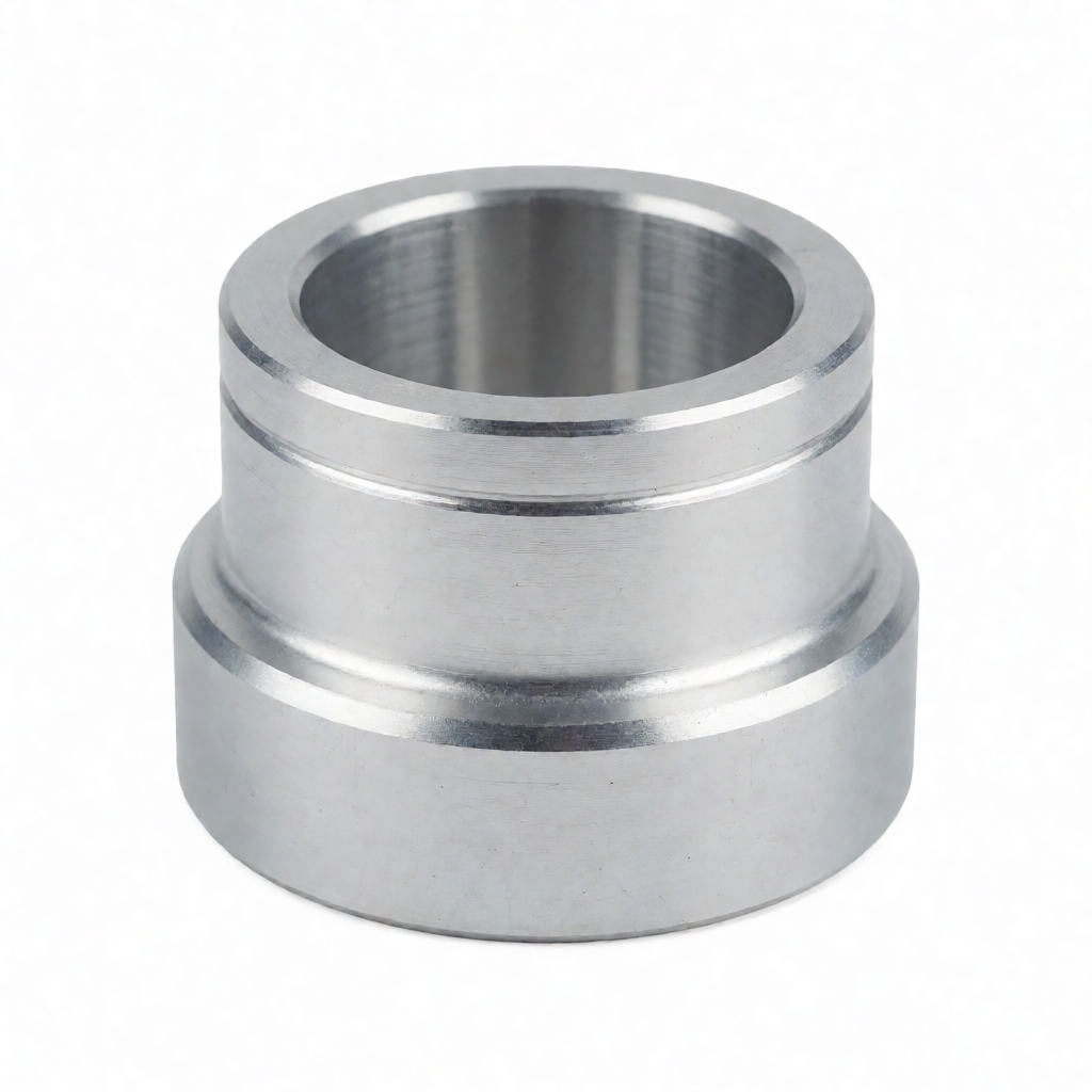
Feasibility Assessment of Multi-axis Linkage in the Design of Complex Structure CNC Parts
For complex CNC parts involving non-planar contours, deep cavities or narrow and long wall structures, traditional three-axis machining is often limited by tool path interference, accessibility blind spots and the risk of clamping deformation. By introducing 4-axis or 5-axis linkage technology, the one-time clamping processing capability for complex geometric features can be significantly enhanced, thereby maintaining reference consistency and shortening the process flow. However, the application of multi-axis linkage is not multi-purpose. Its value depends on the specific geometric complexity of the parts, material properties, and production batch. This article aims to provide a systematic feasibility assessment framework from the perspective of engineering design and manufacturing processes, helping engineers and purchasers accurately determine whether to adopt a multi-axis solution in the early stage of a project, and avoiding overdesign or undermatching of processes.Multi-axis machining requirement determination based on geometric features
Before deciding to adopt multi-axis machining, the primary task is to conduct an in-depth analysis of the geometric features of the parts. Not all non-planar structures require 5-axis linkage. Many inclined surfaces or step structures can be efficiently addressed through 4-axis indexing. The key lies in identifying whether there are features of "multi-faceted intersection" and "needing to be completed in one clamping", or whether there are cavities with an extremely large depth-to-diameter ratio and inclined side walls.Key geometric criteria
- Deep cavity and stepped shaft: When the depth-to-diameter ratio of the inner cavity (D/d) is greater than 3 and the side wall has an inclination Angle of more than 15 degrees, 3-axis milling is prone to cause the tool overhang to be too long, resulting in chatter marks or tool deflection. At this point, the use of 5-axis side milling can shorten the tool overhang and enhance rigidity.
- Multi-directional features: If the part has features that need to be milled in four directions other than the positive Z-axis direction (such as the bottom through hole side wall, inclined mounting surface), and these features need to maintain a high coaxiality or positional tolerance (such as within ±0.02mm), indexing processing may introduce cumulative errors due to multiple clamps. At this time, 5-axis linkage has a significant advantage.
- Freeform surface: For parts with continuously varying radii of curvature (such as impellers, turbine blades, and medical orthoses), the 3-axis can only use small-diameter ball cutters for corner cleaning, which is extremely inefficient and difficult to ensure the smoothness. 5-axis linkage enables the use of large-diameter tools for fine machining with smaller step distances, significantly improving surface quality.
Comparative Analysis of 4-Axis and 5-Axis Linkage Schemes
In actual production environments, 4-axis indexing (A-axis or B-axis) and 5-axis simultaneous linkage are two common multi-axis processing modes. There are significant differences in cost, programming difficulty and applicable scenarios between the two. The following table provides a detailed comparison of the two schemes for reference in technical decision-making.| Comparison dimensions | 4-axis Indexing processing | 5-axis Simultaneous (5-axis Simultaneous) |
|---|---|---|
| Exercise mode | While the X/Y/Z axes move, the A/B axes undergo angular indexing (pause), which is a discontinuous motion. | Simultaneous continuous interpolation motion of the X/Y/Z/A/B axes maintains the tool posture optimization. |
| Applicable scenarios | Step shafts, helical grooves, inclined planes, simple polyhedra; Suitable for parts with large batch sizes and complex single features. | Impellers, cutting tools, aviation structural components, complex molds; Suitable for single-piece and small-batch parts with extremely complex geometers. |
| Tool overhang control | Poor quality. When indexing, it is still limited by the direction perpendicular to the main axis, and the aspect ratio is restricted. | Excellent, it can dynamically adjust the tool posture, always keeping the tool axis pointing in the optimal direction, greatly reducing overhang. |
| Surface quality | There are tool marks caused by inter-shaft pauses, which require subsequent precision milling or polishing. | Smooth transition without pause points, reaching a surface finish requirement of Ra0.4μm or even higher. |
| Programming difficulty | Medium, capable of using the basic 4-axis functions of most CAM software. | The requirements for CAM engineers are extremely high, as they need to take into account singularities, interference checks, and tool posture optimization. |
| Equipment utilization rate | High, fast indexing action, suitable for mixed production. | Relatively low, the linkage trajectory calculation is complex, and the chip time is often long. |
The influence of material properties on multi-axis cutting strategies
The feasibility of multi-axis linkage not only depends on the geometric shape but is also closely related to the cutting performance of the material. The thermal deformation, tool sticking tendency and residual stress distribution of different materials under high-speed continuous motion are all different, which directly affect the planning parameters of multi-axis paths.Cutting considerations for Metallic Materials
For aluminum alloys (such as 7075-T6), they have a high thermal conductivity but relatively weak tool adhesion, making them suitable for high-speed, deep cutting, and multi-axis precision machining. However, attention should be paid to heat accumulation during high-speed movement. For stainless steel (such as 304/316), the cutting hardening effect is obvious. When multi-axis linkage is carried out, it is necessary to avoid the tool repeatedly cutting in the hardened layer. It is recommended to adopt a helical interpolation path and ensure that the 5-axis posture makes the tool tip entry Angle greater than 0 degrees to optimize chip breaking. Titanium alloy (Ti-6Al-4V) is a typical multi-axis beneficiary material. Due to its poor thermal conductivity, 3-axis machining is prone to cause the tool head to overheat and chipping. 5-axis side milling can effectively disperse cutting heat and allow for the use of shorter tools, thereby ensuring the stability of deep cavity machining.The Particularity of engineering plastics
When processing high-temperature engineering plastics such as PEEK and PAI, the significance of multi-axis linkage lies in reducing the heat accumulation time. Due to the low thermal conductivity of plastic, prolonged retention can lead to local melting. 5-axis linkage can quickly complete cutting through optimized feed speed and attitude, reducing the risk of workpiece thermal deformation. In addition, plastic materials have relatively low rigidity. Special attention should be paid to the clamping method during multi-axis processing to avoid elastic deformation of the workpiece during processing due to clamping force, which may affect dimensional accuracy.Simulation Verification of clamping Interference and Accessibility
Theoretically feasible multi-axis paths may fail to be executed on actual equipment due to spatial interference among workpieces, fixtures, and headstock. Therefore, during the CNC programming stage, full-machine simulation must be carried out.Key points of interference inspection
- Fixture interference: Calculate the safe distance between the maximum outer diameter of the fixture and the edge of the machine tool worktable and the lower box after the workpiece is clamped. When the 5-axis is in linkage, the change in the workpiece's posture may cause the originally non-interfering fixture components to collide at a specific Angle.
- Spindle box interference: Check whether the spindle taper shank and tool holder interfere with the machine tool slide or protective door when processing in a nearly horizontal direction. Especially when machining the bottom of a deep cavity in a closed space, sufficient space for spindle retraction should be reserved.
- Tool approach/distance movement: Many CAM software programs, when generating multi-axis codes, default to ignoring the approach and distance actions of tools. Engineers need to manually check whether these safe movement paths avoid the workpiece and fixture to prevent tool collision accidents.
Precision maintenance and tolerance accumulation control
One of the core advantages of multi-axis machining is to reduce the number of clamping operations, thereby lowering the accumulation of errors caused by reference conversion. However, the motion accuracy of the multi-axis machine tool itself (such as the positioning accuracy and repeat positioning accuracy of the turntable) will also become a link in the tolerance chain.Error Source Analysis and Compensation
When evaluating multi-axis schemes, the geometric errors of the machine tool need to be incorporated into the tolerance analysis. For instance, if the part requires two side holes 200mm apart to maintain a positional accuracy of ±0.01mm, and these two holes are distributed on two surfaces at 90 degrees to each other. The 3-axis solution requires two clamping processes, with each clamping error being approximately ±0.02mm. The cumulative error may reach ±0.04mm, exceeding the standard. For a 5-axis one-time clamping, although the machine tool's turntable may have an angular error of ±0.005mm, the reference remains unchanged, and the final positional accuracy is usually controlled within ±0.015mm, meeting the requirements. Furthermore, for Ra0. For a surface finish requirement of 4μm, attention should be paid to the step distance of the tool path during multi-axis finishing. Excessive step distance will cause knife marks, directly affecting the appearance quality. It is recommended to keep the step distance within 0.1mm during the precision milling stage and combine it with an appropriate surface finishing strategy to ensure that the appearance is free of scratches and has high luminous efficiency.Economic Assessment: When to Choose Multi-Axis Machining
Technical feasibility must be combined with economic rationality. The investment and operation costs of multi-axis machine tools are significantly higher than those of 3-axis machine tools. Not all complex parts are suitable for 5-axis processing.Cost-benefit analysis dimensions
- Unit value: For high-value parts such as aerospace and medical implants, the combined cost saved by the precision improvement and process consolidation brought about by multi-axis machining (reducing manual loading and unloading and inspection frequency) is often higher than the additional processing fee caused by the machine time difference of multi-axis machining.
- Batch size: For small-batch (such as 10 to 50 pieces) complex parts, multi-axis machining has a comparative advantage because the time cost of programming and trial cutting is spread over each part. However, for large quantities of parts (such as over 10,000 pieces) with relatively regular structures, developing dedicated multi-station combined machine tools or high-rigidity 3-axis machine tools may be more economically viable.
- Urgency of delivery date: If the project requires an extremely short delivery time, multi-axis machining can significantly shorten the production cycle (CT). Taking the joint housing of a certain complex unmanned aerial vehicle as an example, the 3-axis solution requires 5 clamping operations and a total working time of 45 hours. The 5-axis solution requires two clamping operations and has a total working time of 22 hours. When equipment production capacity is tight, multi-axis machining can provide more flexible production scheduling space.



