





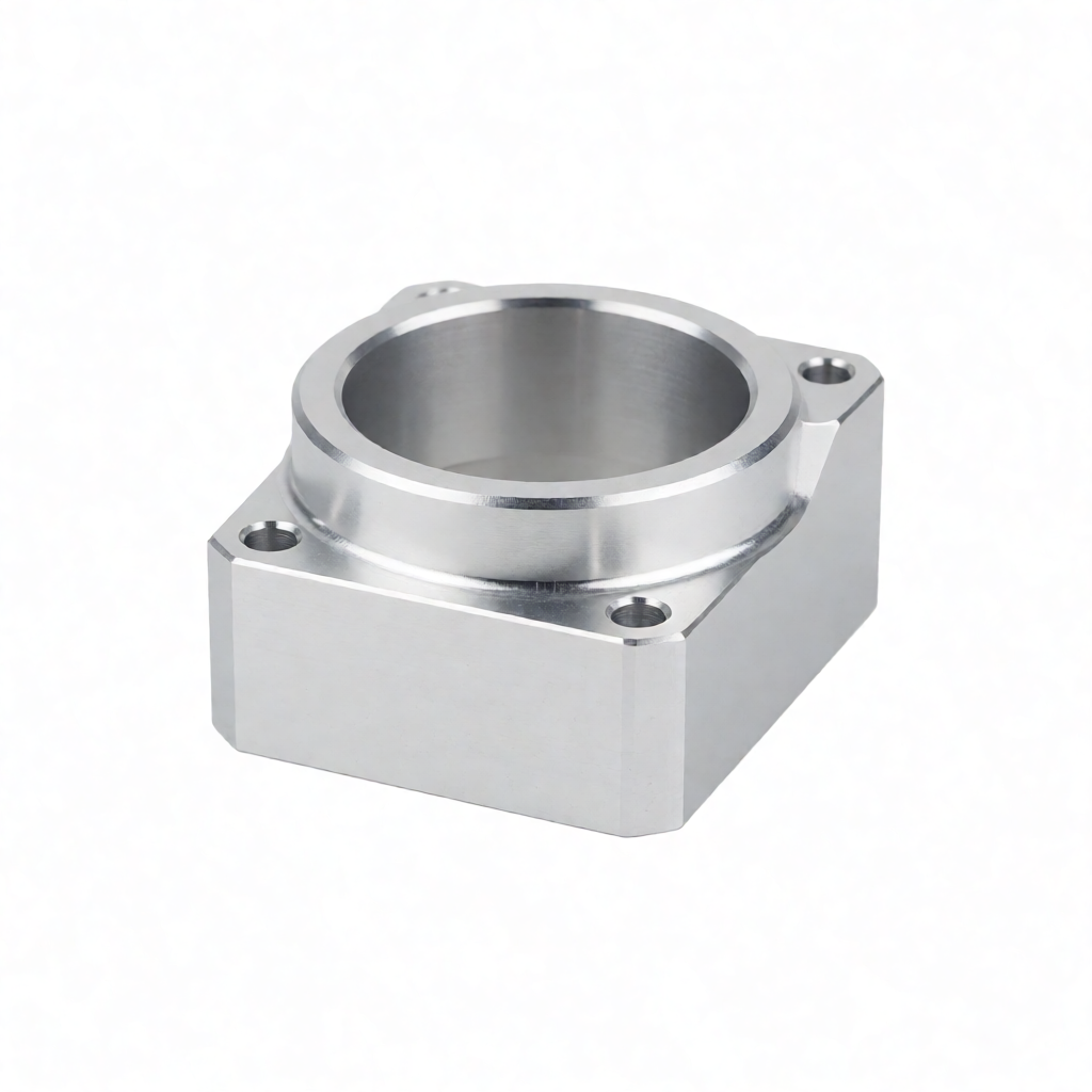
The Gap Between Design and Manufacturing: Why DFM is the First Line of Defense for Precision CNC Parts
In the early stages of custom precision CNC part fabrication, the completeness of engineering drawings directly determines the stability and cost ceiling of subsequent mass production. Many R&D engineers tend to view parts as pure geometries, overlooking the physical constraints imposed by material removal processes. When design drawings lack a manufacturability analysis (DFM), common hidden risks include sharp internal corners, overly thin cantilevered structures, unmarked default tolerances, and complex free-form surfaces that cannot be verified by a coordinate measuring machine (CMM). These defects often surface only after prototyping or even in the early stages of mass production, leading to hidden costs for die modification, program adjustments, or re-fixturing that far exceed the investment in upfront design optimization. For complex parts involving 3/4/5-axis milling, lathe-milling centers, and swiss-type machining, early intervention with a DFM checklist not only mitigates geometric interference risks but also optimizes feature structures to reduce toolpath cycle time, thereby significantly shortening bulk delivery cycles. As a manufacturer with 72 CNC machines, we recommend strictly executing the following engineering review process before drawing freeze to ensure that design intent is converted into high-precision physical parts without loss.
Geometric Structure Review: Avoiding Machining Interference and Stress Concentration Risks
The core of DFM review lies in identifying geometric features that are difficult to realize or prone to failure in CNC machining. Tools have minimum diameter limits; therefore, if sharp internal corners (concave angles) exist within a part, a fillet will inevitably remain after milling, with its radius limited by the tool radius. If the design does not account for this allowance, subsequent deburring or finishing grinding will significantly increase man-hours and reduce surface consistency. Additionally, slender cantilevered beams are susceptible to vibration under cutting forces, which can lead to out-of-spec surface roughness or tool breakage. It is recommended that at the initial stage of structural design, the cantilever ratio be kept within a reasonable range, or support ribs be added and wall thickness tapered to avoid stress concentration. For mating surfaces requiring high precision, deep and narrow slots should be avoided, as heat dissipation and chip evacuation at the bottom of deep slots are difficult, easily inducing thermal deformation and affecting dimensional stability.
Mapping Relationship Between Internal Corners and Tool Radius
Engineers must default to introducing "tool compensation fillets" in their CAD models. If the part requires dimensional accuracy within ±0.01mm, the internal concave corner radius is typically recommended to be no less than 0.8mm (based on the consideration of common minimum finishing end mill diameters of 1.6mm). If the design strictly requires sharp angles, it must specify that subsequent wire EDM or laser cutting will be used for edge trimming, and clearly define the deburring standards for the interface. Ignoring this physical constraint is one of the most common non-human factors causing first-article dimensional deviations.
Tolerance and Surface Finish Callouts: From "Assumed" to "Acceptable"
Unmarked tolerances are a high-frequency hazard in DFM reviews. According to GB/T 1800 or ISO 286 standards, unmarked dimensional tolerances typically follow the IT12 grade, which is clearly too loose for precision assembly parts. If the part is a transmission sleeve, sealing surface, or mating hub, the tolerance zone code (e.g., h6, H7) or specific values for critical dimensions must be clearly marked on the drawing. Simultaneously, surface roughness Ra values should not be treated as decorative callouts only. For surfaces requiring anodizing or plating, if not pre-ground, the microscopic geometric texture will remain on the surface, leading to "snowflake spots" or color variations in the final appearance. It is recommended to specify Ra values for critical functional surfaces (e.g., Ra 0.8μm or Ra 0.4μm) and distinguish between functional and non-functional surfaces. For high-gloss or mirror finish requirements, the specific grade of the polishing process must be noted so that the manufacturing side can arrange the corresponding polishing machine or manual polishing resources, ensuring batch consistency.
Material Selection and Pre-processing: Balancing Machinability and Final Properties
Material selection is not only about the mechanical performance of the part but also directly affects machining efficiency and tool life. Aluminum alloys (e.g., 6061-T6, 7075-T6) have excellent machinability, are easy to finish to high gloss, and are suitable for appearance parts; stainless steels (e.g., 304, 316L) are sticky and prone to work hardening, requiring tools with large chip spaces and reduced feed rates; high-strength steels (e.g., 42CrMo4) impose higher requirements on tool wear resistance. At the DFM stage, the sum of material cost and processing cost must be evaluated. For example, choosing forged aluminum instead of bar stock may reduce material costs, but the risk of internal porosity or shrinkage cavities could increase the scrap rate. If the part requires heat treatment, sufficient finishing grinding allowance must be reserved, and the heat treatment condition (e.g., HRC hardness range) must be marked on the drawing to avoid dimensional drift caused by the release of residual stress. For engineering plastics (e.g., PEEK, PEI), attention must be paid to their coefficient of thermal expansion and hygroscopicity; design should consider temperature compensation for assembly clearances.
Fixturing Strategy and Process Route Prediction: Making "Invisible" Processes Visible
Processing strategies often determine the final form limits of the part. Many design drawings do not consider how the workpiece will be held in the machine. If all faces of the part have dimensional or roughness requirements and there is no suitable datum surface, auxiliary fixtures (e.g., vacuum adsorption, soft jaws, adhesive bonding) will be required. The development and tuning of such fixtures will significantly extend the prototyping cycle and increase costs. In the DFM check, the machinability of the "third" or "fourth" datums should be identified. For example, for slender shaft parts machined on swiss-type lathes, the design of the tailstock center contact surface or support structure must be clearly defined to prevent deformation of the machined section due to its own weight. For multi-axis machining (4/5 axes), the motion envelope of the tool and spindle in any orientation must be confirmed to avoid collisions between the tool and the workpiece or fixture. Clarifying these process details helps in reaching consensus with the manufacturer in advance through annotations or appendices on the drawing, avoiding process rework during mass production.
Comparison of Common DFM Defects and Optimization Solutions
The table below summarizes common DFM defects from the R&D side, their impact on the manufacturing side, and provides specific optimization suggestions. By cross-referencing this table, engineers can quickly identify potential risk points in their design drawings and complete self-correction before submitting an inquiry.
| Defect Type | Specific Manifestation | Manufacturing Impact | Optimization Recommendations (DFM Correction Direction) |
|---|---|---|---|
| Unspecified Internal Fillets | Internal concave corners are specified as 90° sharp angles without indicating the tool radius | CNC end mills cannot machine sharp internal corners, requiring additional wire EDM or manual deburring, which significantly increases cost and reduces consistency | Specify internal fillets of 0.5-1.0mm (based on tool specification) or annotate "Chamfer C0.5" and define the deburring standard |
| Deep Narrow Slot Design | Slot width <1mm, aspect ratio> 8:1, no chip evacuation structure | Tools are prone to breakage, heat accumulation causes workpiece thermal deformation, making dimensional accuracy difficult to control | Optimize slot shape to trapezoidal, add chip evacuation holes, or machine the deep slot in sections to reduce single-pass cutting depth | No Datum Features | All faces have dimensional requirements, and the geometry is symmetric with no obvious clamping datum | Requires custom tooling and fixtures, leading to long debugging cycles and large positioning errors in batch production | Design non-functional locating surfaces or pin holes, reserve 1-2 planar surfaces as clamping datums, or specify the clamping method on the drawing |
| Mixed Material Interfaces | Metal parts must be precision-assembled with plastic parts without considering thermal expansion differences | Temperature changes alter fit clearance, leading to assembly failure or stress cracking | Recalculate assembly clearance, select materials with matched coefficients of thermal expansion, or design a floating hinge structure |
Acceptance Criteria and Inspection Methods: The Final Step of Closed-Loop DFM
The ultimate goal of DFM is to establish executable acceptance criteria. The drawing must clearly specify inspection methods for critical dimensions. For conventional dimensions, calipers and micrometers are sufficient; for geometric tolerances (such as concentricity, flatness, and profile), specify the use of a Coordinate Measuring Machine (CMM) or dedicated gauges. If the part involves micro-structures (such as heat sink fins, small threads), specify the evaluation length for the roughness tester (typically 4mm) and filtering rules. Furthermore, for appearance-critical parts, define defect tolerance levels (e.g., "no scratches, no color variance, no flow marks") and define acceptable standards by referencing the surface finishing process specification. It is recommended that engineers add a "Quality Characteristics" list to the drawing, listing KPC (Key Product Characteristics) dimensions that affect function and safety, to allow the manufacturing side to implement SPC (Statistical Process Control) during the process. This closed-loop mechanism not only improves acceptance efficiency but also solidifies DFM optimization results into the enterprise's standard process library through data traceability.
FAQ: Common Questions About DFM Check and CNC Machining
Will DFM check increase the preliminary development time of the project?
Although it adds a review stage on the design side, it typically shortens the overall project cycle by 20%-30% by avoiding process changes and rework during mass production. Exposing manufacturing difficulties early is more time-efficient than discovering them during prototyping and having to re-tool.
If the drawing is already frozen, can DFM optimization be performed directly?
Yes. The manufacturer's DFM engineer will perform reverse analysis based on the existing drawing, identify potential machining risks, and propose optimization suggestions with minimal changes. This requires close communication between the design and manufacturing teams to ensure changes do not affect the original functionality.
Which structures are most suitable for swiss-type lathe machining?
Shaft and sleeve parts with an aspect ratio greater than 4:1 and small diameters (typically 1-20mm) requiring high precision. Swiss-type lathes provide dual support, which significantly reduces deflection of slender parts, ensuring concentricity and surface finish.
Will DFM suggestions affect the standardization level of parts?
Effective DFM suggestions aim to simplify non-standard structures to make them easier to standardize for machining. For example, unifying internal fillet specifications and standardizing thread depth actually helps improve production efficiency and interchangeability.
What special requirements does surface treatment have for DFM?
Consider the impact of plating thickness on dimensions (e.g., electroplating increases radial dimensions) and the impact of anodizing on internal threads (typically requires a 0.1mm allowance on the thread root or using a spray coating process). The drawing must specify the final dimensional requirements after surface treatment.
Conclusion and Action Recommendations
DFM is not a one-time design action but an engineering mindset that spans the entire product lifecycle. By front-loading geometric constraints, tolerance logic, material properties, and process routes into the design phase, companies can effectively reduce trial-and-error costs and improve the reliability of batch delivery. If you have drawings for precision CNC parts awaiting mass production, it is recommended to immediately execute the checklist above. For custom requirements involving complex 3/4/5-axis multi-face parts, Swiss-type slender shafts, or appearance parts requiring high surface finish, please send your 3 Inquiry via 3D model or 2D drawings: leveraging the production capacity layout of our 72 CNC machines, we provide you with a professional solution that includes DFM optimization suggestions, tolerance analysis, and batch delivery time evaluation.



