





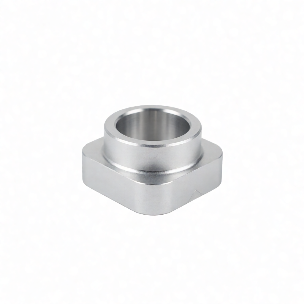
Core Engineering Considerations for Blast-Proof Design in CNC Machined Battery Housings
Against the backdrop of the growing adoption of lithium batteries and energy storage systems, the battery housing serves as a critical safety barrier, where its structural design directly impacts resistance to thermal runaway and pressure venting capabilities. Many engineers overlook the impact of material thickness, wall uniformity, and edge finishing on vent valve response accuracy during the drafting stage, leading to stress concentration or assembly interference in subsequent CNC machining. This article focuses on the practical logic of blast-proof design for CNC machined battery housings, providing actionable technical solutions covering structural parameters, material selection, machining processes, and acceptance criteria. The main keyword “cnc machined battery housing blast-proof design” runs throughout the text to help procurement and R&D personnel quickly locate critical process nodes.
Key Dimensional Parameters and Tolerance Definitions for Blast-Proof Structures
Blast-proof design for battery housings begins with defining the geometric parameters of the vent path. Typically, the vent hole diameter for cylindrical battery housings ranges from 1.2mm to 2.0mm, while vent slot widths in rectangular housings commonly range from 0.5mm to 1.5mm. These dimensions must account for a manufacturing tolerance of 0.02mm to 0.05mm to ensure that the sealing gasket does not completely close the vent path after assembly. Wall thickness uniformity requires deviation control within ±0.05mm to avoid premature rupture at thin sections during thermal expansion, which would lead to uncontrollable venting.
- Vent hole location: It is recommended to position the vent hole at the axial center of the housing, at a distance of ≥15mm from the end cap sealing surface to avoid edge stress interference.
- Chamfering: A chamfer of 0.2mm to 0.5mm at the vent hole entrance reduces stress peaks during the installation of plugs or diaphragms.
- Housing thickness: For aluminum alloy housings, a wall thickness of 1.0mm to 1.5mm is recommended. For steel housings, the thickness can be increased to 2.0mm to balance strength and weight.
These parameters must be aligned with thermal simulation data before CNC programming to ensure the machined dimensions match the simulated critical venting point. Setting tolerances too tight increases machining costs, while looser tolerances affect the consistency of vent valve actuation.
Impact of Material Selection on Blast-Proof Performance and Machinability
Common materials for battery housings include 6061-T6 aluminum alloy, 304 stainless steel, and engineering plastics (such as PBT, PA+GF). Different materials exhibit significant differences in CNC machinability, thermal conductivity, and cost, directly affecting the feasibility of the blast-proof design.
| Material Grade | Density (g/cm³) | Thermal Conductivity (W/m·K) | CNC Machinability | Compatibility with Blast-Proof Design |
|---|---|---|---|---|
| 6061-T6 Aluminum | 2.70 | 201 | Excellent, suitable for high-speed cutting | High thermal conductivity aids heat dissipation; suitable for high-power cells |
| 304 Stainless Steel | 7.93 | 16.3 | Poor, requires low speed and high torque | High strength and pressure resistance; suitable for high-voltage energy storage systems |
| PBT+GF30 | 1.50 | 0.25 | Good, burr control required | Excellent insulation and light weight; suitable for consumer electronics |
For blast-proof design, the high thermal conductivity of aluminum helps slow the spread of thermal runaway; however, its lower strength necessitates rib reinforcement around the vent holes. Stainless steel offers high strength but poor thermal conductivity, making it suitable for high pressure resistance applications. Engineering plastics provide good insulation, but high-temperature deformation and shrinkage rates must be considered, with shrinkage compensation accounted for during CNC machining.
CNC Machining Process Path and Implementation of Blast-Proof Features
CNC machining of battery housings typically involves a combination of multiple processes: milling for shaping → turning for finish machining → drilling/tapping → surface treatment. The sequence of machining blast-proof features is critical; vent holes are recommended to be drilled after rough machining but before finish machining to facilitate subsequent corner cleaning and deburring.
Application Boundaries of 3-Axis and 4-Axis Machining
Simple cylindrical housings can be machined on a 3-axis machining center. However, complex housings with side reinforcement ribs or inclined vent slots require 4-axis coordinated machining to avoid tool interference. Recommended spindle speeds are 8000–12000rpm for aluminum parts and 3000–5000rpm for stainless steel parts. Feed rates should be adjusted according to tool diameter to ensure a surface roughness of Ra≤0.8μm, reducing frictional wear on sealing surfaces.
Key Machining Precautions
- Fixture Design: Use vacuum chucks or custom soft jaws to avoid local clamping stress deformation, which affects wall thickness uniformity.
- Coolant: Use water-soluble cutting fluid for aluminum parts and high-temperature, corrosion-resistant coolant for stainless steel parts to prevent chip adhesion to the tool.
- Deburring: Perform ultrasonic deburring on pressure relief hole edges to remove burrs ≥0.1mm in length, preventing damage to the membrane during installation.
Compatibility Analysis of Surface Treatment and Explosion-Proof Function
Surface treatment affects not only appearance but also directly impacts the long-term reliability of the explosion-proof valve. Anodizing is the preferred treatment for aluminum alloy battery shells, but attention must be paid to the impact of oxide film thickness on dimensional tolerances.
Standard anodized film thickness is typically 8μm to 15μm. If design tolerances do not account for this allowance, machining dimensions must be reduced inward by the corresponding value. Sandblasting can improve the shell's grip feel, but pressure relief hole areas must be masked to prevent sand particles from clogging the channels. Nickel or zinc plating is mainly used for stainless steel shells to prevent corrosion, but film uniformity must achieve ±0.5μm to avoid local weak points.
Expert Tip: After anodizing, a 100% full dimensional inspection is recommended before shipment, particularly for pressure relief hole position and diameter, as film thickness causes slight shrinkage of the hole diameter, affecting burst pressure calibration.
Common Failure Modes and Mitigation Strategies
Common explosion-proof failure modes in battery shell CNC machining include: misalignment of pressure relief holes, residual burrs, and unexpected rupture caused by non-uniform wall thickness. These defects often appear covertly in mass production and require monitoring through Statistical Process Control (SPC).
- Pressure Relief Hole Misalignment: Often caused by worn locating pins in fixtures or deviations in the programming coordinate system. Mitigation: Calibrate locating pins every 50 parts and use an automatic tool setter.
- Residual Burrs: Hard materials or high-speed drilling easily produce internal burrs. Mitigation: Add a reaming operation after drilling or use a grooving cutter for cleaning.
- Non-Uniform Wall Thickness: Caused by gas porosity in cast blanks or tool deflection during machining. Mitigation: Increase wall thickness sampling points during incoming material inspection and reserve a 0.1mm machining allowance.
To address these failures, it is recommended to include burst test samples during First Article Inspection (FAI), recording the deviation between actual burst pressure and theoretical values as a baseline reference for mass production.
Acceptance Criteria and Inspection Report Requirements
Final acceptance must cover three dimensions: dimensional accuracy, surface quality, and functional verification. Dimensional tolerances are recommended to follow the ISO 2768-mH standard, with critical explosion-proof feature tolerances marked on the drawing. Surface quality requires no scratches or oxidation spots, with a gloss deviation ≤5GU at a 60° angle.
Functional verification includes airtightness testing (0.5MPa air pressure, held for 30 seconds with no leakage) and burst testing (performed on a sampling basis, recording burst pressure). Inspection reports should include Coordinate Measuring Machine (CMM) data, roughness meter readings, and surface treatment thickness measurements. It is recommended that suppliers provide complete process parameter records to facilitate batch traceability.
Quality Control Milestones in Mass Production
Within the 15-25 day mass production cycle, it is recommended to set up full dimensional inspections at the first piece, mid-batch, and final batch milestones, using a combination of CMM and optical measuring instruments to ensure dimensional drift is under control. Surface appearance requires 100% visual inspection with light box assistance, focusing on checking for defects in the explosion-proof area.
FAQ: Common Questions on Explosion-Proof Design for Battery Shell CNC Machining
What should the tolerance for pressure relief holes be when CNC machining battery shells?
It is recommended to set the tolerance at ±0.02mm to ±0.05mm, depending on the membrane installation method. Excessively tight tolerances increase machining difficulty, while excessively loose tolerances affect seal consistency; assembly clearance calculations must be considered.
Can aluminum alloy battery shells be chrome-plated after CNC machining?
Not recommended. Direct chrome plating of aluminum alloys requires pre-plating (immersion), a complex process where the coating is prone to peeling, affecting the flatness of the explosion-proof surface. Anodizing or hard anodizing treatment is recommended as the priority.
How to improve the wall thickness uniformity of CNC machined battery shells?
Optimizing fixture design to reduce deformation, performing 100% wall thickness inspection of blanks during incoming material checks, reserving uniform machining allowances, and adding tool deflection compensation parameters to the program are key to improving uniformity.
What is the required surface finish for the explosion-proof valve mounting surface?
Ra≤0.4μm to Ra0.8μm is recommended to ensure the membrane fits completely without warpage. Excessive roughness causes local stress concentration, leading to premature rupture and affecting the explosion-proof pressure threshold.
What is the minimum order quantity (MOQ) for CNC machined battery shells?
Depending on process complexity, single-piece prototyping is feasible, but mass production is usually more cost-effective starting from a few dozen pieces. Specific requirements depend on tool wear rates and programming time; please refer to our process evaluation workflow.
Conclusion and Action Recommendations
The explosion-proof design of battery shell CNC machining is the result of coordinated structure, material, and process; negligence in any single link may lead to safety failures. By defining precise dimensional tolerances, rational material selection, standardized machining paths, and strict quality acceptance, the safety and consistency of battery shells can be significantly improved. It is recommended that engineers intervene in CNC process reviews during the R&D stage to avoid cost and delivery risks associated with later modifications. If you need to evaluate the machinability and explosion-proof performance of existing drawings, you can send detailed drawings and technical requirements to obtain a quick quote and DFM suggestions based on actual equipment and process capabilities.



