





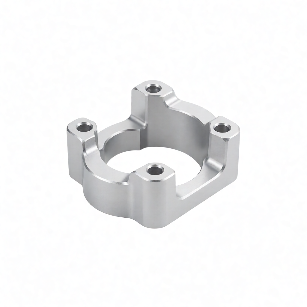
Titanium alloy, with its low density, high strength, and excellent corrosion resistance, has become a core material in aerospace component manufacturing. However, the difficulties in CNC machining aerospace titanium alloy components extend far beyond the single dimension of high hardness, encompassing material chemical reactivity, cutting heat management, tool wear mechanisms, and microstructural deformation. For engineers and procurement personnel involved in aerospace structural component manufacturing, understanding these challenges is key to evaluating a supplier's true process capability. Based on actual production experience, this article provides an in-depth analysis of the core challenges of commonly used titanium alloys such as Ti-6Al-4V in CNC machining, and offers validated engineering solutions and acceptance criteria.
The Fundamental Impact of Titanium Alloy Material Properties on the Machining Process
Compared with traditional aluminum alloys or steels, titanium alloys are a typical class of "difficult-to-cut" materials. Their core challenges stem from three physical properties: low thermal conductivity (approximately 45 W/m·K, only 1/7 that of aluminum), low elastic modulus (approximately 100 GPa, only 1/5 that of steel), and high chemical reactivity. During the CNC cutting process, most of the cutting heat cannot be carried away by the chip; instead, it accumulates at the tool edge and workpiece surface, causing the local temperature to rapidly rise above 600°C. This intensifies tool diffusion wear and chemical wear. At the same time, due to the low elastic modulus, the workpiece is prone to elastic deformation under cutting forces; if clamping is not properly executed, it is easy to produce a "tool deflection" phenomenon, causing machining accuracy to exceed allowable tolerances. In addition, at high temperatures, titanium reacts with elements such as oxygen and nitrogen, forming a brittle oxide layer that affects surface integrity and fatigue life. Therefore, when selecting tools, one must not only look at hardness but also pay attention to the high-temperature stability of the tool coating. For example, nano-ceramic composite coatings or AlTiN coatings have far superior oxidation resistance to ordinary TiAlN coatings.
Coordinated Control of Spindle Speed, Feed Rate, and Coolant
The core strategy to address thermal effects in titanium alloy machining is to combine "low speed, high depth of cut" with efficient cooling. Excessive spindle speed leads to a sharp rise in tool tip temperature, accelerating the degradation of tool life. Generally, when milling Ti-6Al-4V, keeping the spindle speed in the range of 500-1500 rpm is a prudent approach, with specific calculations required based on the tool diameter to determine the cutting speed (Vc 30-60 m/min). The feed rate should not be too fast to avoid chatter, nor too slow to prevent deep tool marks. More importantly is the choice of cooling method. Dry machining or minimal quantity lubrication (MQL) is strictly prohibited for titanium alloy processing; instead, high-pressure micro-lubrication (HPL) or total immersion cooling with a large volume of coolant must be used. High-pressure nozzles (typically with pressure >70 bar) can spray coolant directly onto the separation point between the chip and the tool, effectively keeping the cutting zone temperature below 300°C and preventing thermal damage. If only ordinary low-pressure spraying is used, the coolant cannot reach the root of the chip, greatly reducing the cooling effect and potentially shortening tool life by more than 50%. In engineering practice, it is recommended to prioritize water-soluble cutting fluids, with a concentration controlled at 5%-10% and equipped with anti-rust properties to prevent white rust from appearing on the titanium component surface.
Technical Details of Tool Selection and Clamping Accuracy
Tool selection is one of the decisive factors for the success of CNC machining of titanium alloys. For common cavity, slot milling, and drilling operations on aerospace parts, solid carbide tools are the mainstream choice. For rough machining, it is recommended to use tools with a large helix angle (e.g., 45°) or an unequal-pitch design to break periodic impact and reduce vibration. For finish machining, solid or indexable end mills with a large rake angle and small clearance angle should be used to enhance cutting edge strength. When drilling, special titanium alloy drill bits must be used, such as cobalt-containing high-speed steel (HSS-Co) or solid carbide drills. The drill point angle is typically 90°-118°, and the chip flutes need to be widened to accommodate the tough titanium chips. Clamping accuracy is equally critical. The low elastic modulus of titanium alloy means that any clamping deformation will recover after release, leading to dimensional out-of-tolerance. Therefore, precision clamps such as hydraulic chucks or custom soft jaws must be used, ensuring that the flatness of the locating reference surface is within 0.02 mm. For thin-walled parts, vacuum suction or flexible support clamps can be used to avoid localized stress concentration. Tool runout should be controlled within 0.01 mm; otherwise, excessive cutting force on one side will accelerate wear.
Comparison of Efficiency and Quality of Different Machining Process Routines
For different types of titanium alloy aerospace parts, the choice of process route directly determines cost and delivery time. Below is a comparative analysis of three mainstream processes: milling, turning, and turning-milling composite machining, for reference in procurement and technical evaluation:
| Process Type | Applicable Part Shape | Typical Tolerance Level | Main Difficulties and Countermeasures | Economic Analysis |
|---|---|---|---|---|
| 3-axis/4-axis milling | Planes, cavities, flanges, simple irregular parts | ±0.02 mm (IT7-IT8) | Difficult heat dissipation, prone to chatter. Countermeasures: Optimize tool path, use climb milling, enhance cooling. | High equipment availability, low cost per unit, suitable for large-batch standard parts. |
| CNC turning | Shaft-type, sleeve-type, rotationally symmetrical parts | ±0.01 mm (IT6-IT7) | High deformation in thin-walled parts. Countermeasures: Use specialized gripping method, split into roughing and finishing passes, and retract promptly. | High efficiency, high material removal rate, suitable for parts with a large length-to-diameter ratio. |
| Turning-milling machining center / 5-axis simultaneous | Complex structural parts, impellers, shafts with cross-holes | ±0.005-0.01 mm (IT5-IT6) | Complex programming, high risk of tool interference. Countermeasures: rigorous simulation, use of short tool holders, and multi-axis simultaneous compensation for thermal errors. | Multi-face machining completed in a single setup reduces cumulative error. Although the unit price is high, the total cost is optimized, making it suitable for high-value complex parts. |
As shown in the table, while 5-axis turning-milling machining centers place extremely high demands on programming and operator skill, for aerospace fasteners or brackets with complex curved surfaces and radial holes, they significantly reduce the number of setups, thereby ensuring concentricity and shortening lead times. For simple shaft parts, 2-axis turning with tailstock support is typically the best value-for-money option. The key point is that regardless of the machining process, parameters must be optimized to account for the low thermal conductivity of titanium alloys to avoid blindly applying machining habits developed for steel.
Surface Integrity Control and Residual Stress Management
Aerospace-grade titanium alloy parts require not only dimensional accuracy but also strict control of surface integrity. Excessive depth of the work-hardened layer or residual tensile stresses will significantly reduce part fatigue life. During milling, tool wear causes fluctuations in cutting force, leading to sub-microscopic plastic deformation on the surface and the formation of a work-hardened layer. Typically, the depth of the milling work-hardened layer in Ti-6Al-4V ranges between 50-100 μm; if it exceeds 200 μm, subsequent grinding or laser stress-relief treatment may be required. Regarding residual stress, roughing should leave at least 0.5 mm of finishing allowance to remove most of the internal stresses. During finishing, small depth of cut (0.1-0.3 mm) and high feed rates should be used to minimize cutting forces. Additionally, post-machining surface roughness directly impacts fatigue performance. For areas with high stress concentration (such as hole edges or near welds), surface roughness of Ra ≤ 0.8 μm, or even Ra 0.4 μm, is recommended. This typically requires supplementary finishing or polishing operations. During inspection, in addition to using CMMs for geometric dimensions, ultrasonic phased-array or X-ray diffraction methods should be used to detect the surface compressive/tensile stress state, ensuring compliance with airworthiness standards such as AS9102D.
Common Failure Modes and Quality Acceptance Criteria
In the acceptance of titanium alloy CNC-machined parts, common quality defects and their causes are as follows:
- Dimensional Deviations: Primarily caused by thermal deformation or clamping deformation. During acceptance, dimensions must be measured after the part has reached equilibrium at room temperature for 24 hours to avoid thermal expansion errors.
- Surface Scratches / Tool Marks: Caused by chipping of the tool edge or inadequate chip evacuation. During acceptance, use magnifying glasses or optical comparators to inspect, requiring no visible continuous tool marks and meeting roughness specifications.
- Microcracks: Result from stress concentration or inherent material defects. Acceptance testing requires Penetrant Testing (PT) or Magnetic Particle Testing (MT), with 100% inspection performed on critical load-bearing components.
- Tool Marks: Caused by improper feed rates or low spindle speeds. Manifests as periodic dimples. Acceptance involves checking the direction and uniformity of the surface texture.
For aerospace customers, it is typically required to provide complete Material Test Reports (MTR), First Article Inspection (FAI) reports, and process records. MTRs must include chemical composition, mechanical property data, and heat treatment condition. FAIs must strictly adhere to AS9102D standards, documenting actual values for all Key Product Characteristics (KPC) and Key Characteristic Conditions (KCC). Qualified suppliers should be able to provide Cpk data based on SPC (Statistical Process Control), demonstrating a Process Capability Index Cpk ≥ 1.67 to ensure lot consistency.
FAQ: Common Questions on Titanium Alloy CNC Machining
Why do titanium alloy parts discolor after machining? How can this be avoided?
Discoloration is usually caused by high-temperature oxidation or contamination from cutting fluids. To avoid this, keep the workpiece clean throughout the process, use clean rust-prevention oils or water-soluble protective films, and control machining temperatures. If discoloration has already occurred, it can be restored through pickling and passivation, but the impact on surface integrity must be assessed.
How to prevent deformation when machining thin-walled titanium alloy parts?
Adopt a process sequence of "semi-finishing turning - semi-finishing milling - finishing turning - finishing milling" to release stress gradually. Leave 0.1-0.2 mm allowance before final finishing. During clamping, avoid concentrated stress by using shim plates or spring clamps, and perform frequent tool retracts during machining to allow the part to recover its elasticity.
How to prevent drill bit breakage when drilling titanium alloys?
Titanium chips are ductile and tend to wrap around the drill. Use drills with large chip clearance flutes and employ an intermittent feed (peck drilling) method, retracting to clear chips after every certain depth (e.g., 2x the drill diameter). Ensure high-pressure coolant is directed at the drill point and maintain the drill point sharpness.
What is the minimum order quantity for titanium alloy CNC machining?
This depends on supplier capacity. Typically, professional CNC factories support low-volume customization, even single-unit prototyping. Factories like ShowyMetal, equipped with 72 CNC machines, can flexibly handle orders ranging from 1 unit to several thousand, optimizing scheduling to balance cost and lead time.
How to verify if a supplier has experience in titanium alloy machining?
Request suppliers to provide past examples of titanium alloy parts machined, including MTRs, FAI reports, and Spc data. Observe whether their workshop is equipped with high-pressure
The cooling system, whether the tool library is equipped with dedicated titanium alloy tools, and whether the AS9102D standard is enforced. An experienced supplier can clearly explain the heat deformation control strategy.
In summary, the process challenges for CNC machining of titanium alloy aerospace parts lie in balancing thermal management, dimensional stability, and surface integrity. Successful machining relies on fine parameter settings, a dedicated tool cooling system, and a strict inspection process. For buyers, selecting a manufacturer equipped with full-dimensional inspection capabilities (CMM, surface roughness meter, etc.) that can provide complete quality traceability documentation is key to ensuring the reliability of aerospace parts. If you have specific titanium alloy drawings or structural part requirements, you may send 2D/3D files for process evaluation and quotation; we will provide optimization suggestions combined with DFM analysis.



