





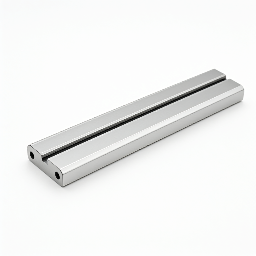
Control points of straightness and parallelism of CNC machining guide rail
In precision CNC machining guides, straightness and parallelism are the core indicators that determine the accuracy and life of mechanical motion. For automation equipment, semiconductor wafer transfer mechanisms, or high-end machine tool slides, the form and position tolerances of guide assemblies are directly related to the repeated positioning accuracy of the equipment. This article will analyze in depth how to control the straightness within 0.01mm/1000mm through multi-axis CNC milling, material selection and inspection processes, and ensure that the parallelism of the slider mounting surface meets the stringent assembly requirements.
Engineering significance and failure mode of geometric tolerance of guide rail
Influence of straightness deviation on motion accuracy
The straightness error of the guide rail is directly converted into an offset of the slider trajectory. When the straightness exceeds the allowable value, the load is unevenly distributed along the entire length of the guide rail, resulting in local stress concentration and accelerated wear of the raceway or sliding surface. In high-speed applications, the straightness error also causes vibration, which reduces the response speed of the equipment. Generally, precision grade guide rails require that the straightness error per 1000mm length does not exceed 0.01mm to 0.02mm, and the specific value needs to be determined according to the equipment grade.
Assembly Interference Caused by Bad Parallelism
Parallel error mainly occurs in the double guide structure or slider mounting surface. If the two guide reference surfaces are not parallel, or there is wedge error between the bottom surface of the slider and the reference surface, excessive interference stress will occur during assembly. This not only increases the driving torque, but also may lead to early failure of the guide rail. In actual production, common failure modes include bending caused by thermal deformation, flatness deviation caused by machining reference deviation, and residual deformation after the release of internal stress in the material.
Effect of material selection and internal stress on accuracy
The material selection of guide parts not only involves mechanical properties, but also relates to size stability. Commonly used guide materials include 45 steel, GCr15 bearing steel and high strength aluminum alloy. After plastic deformation of metals, there will be residual microstructure stress in the material. If sufficient stress release treatment is not carried out after processing, these internal stresses will be slowly released in subsequent processes or long-term use, resulting in bending or twisting of the workpiece and direct damage to straightness.
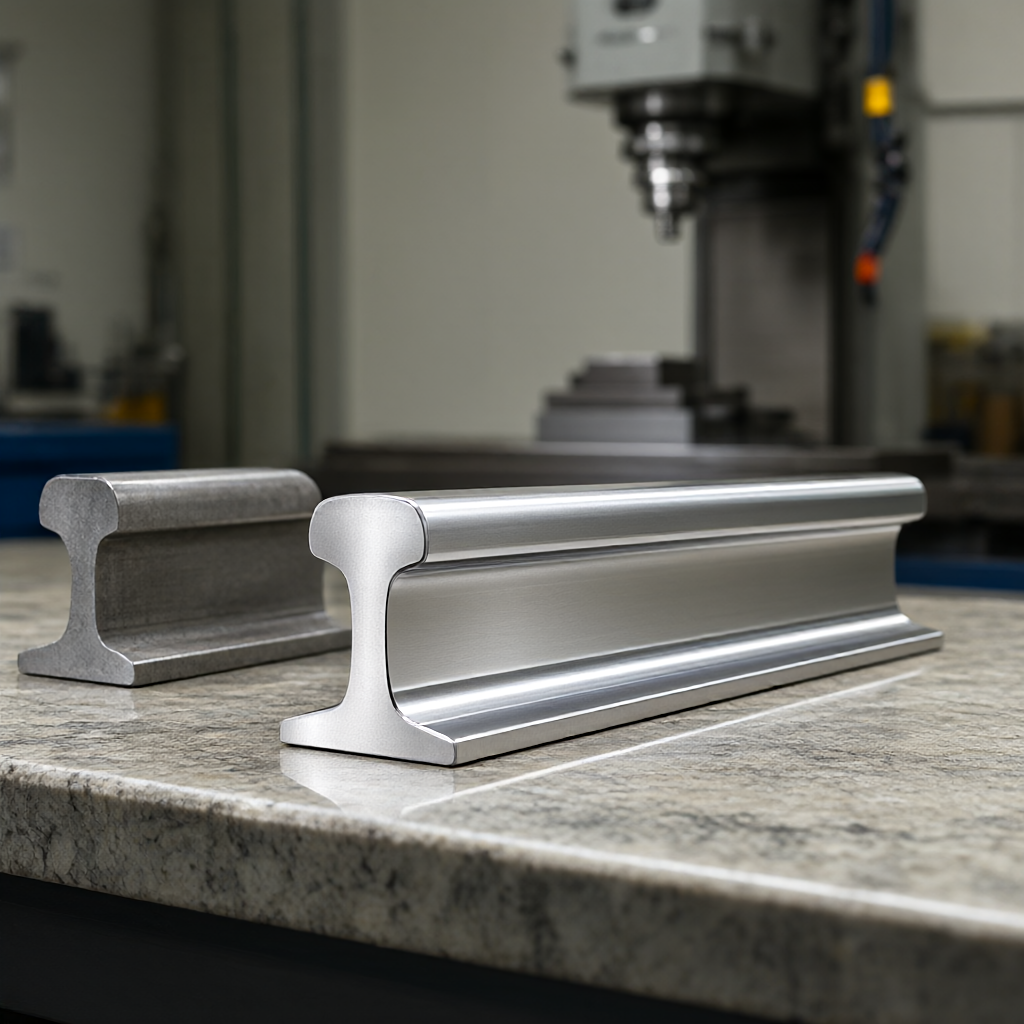
For example, aluminum alloy guide rail, although its weight is light, thermal conductivity is good, but the thermal expansion coefficient is large. After milling, if the ambient temperature fluctuates violently, the machined surface may be slightly deformed due to poor temperature uniformity. Therefore, for high-precision aluminum guide rail, it is usually recommended to carry out low-temperature aging treatment after rough machining, and finish machining and final inspection in a constant temperature chamber (temperature fluctuation control within ±1℃) to offset the error caused by thermal deformation.
Multi-axis CNC machining strategy and optimization of cutting parameters
Programming and setting of cutting parameters are crucial to ensure straightness of guide surfaces. It is common practice to adopt a three-layer cutting strategy of "roughing-semi-finishing-finishing" on 3-axis or 5-axis machining centers. Roughing retains 0.2-0.5mm allowance and mainly removes most of the material; semi-finishing removes most of the allowance and prepares for finishing; Fine machining uses smaller depths of cut (0.1-0.2mm) and moderate feed speeds to achieve good surface finish and size stability.
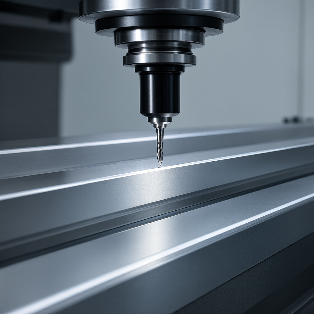
- Tool Selection:Solid carbide end mills are recommended for the finishing stage, usually 6mm to 10mm in diameter and 4-6 teeth for smooth cutting.
- Depth control:The precision cutting depth should be less than 50% of the tool radius to avoid the straightness fluctuation caused by the tool phenomenon.
- Cutting fluid:Sufficient cooling of cutting fluid helps to reduce thermal deformation, but attention should be paid to avoid rapid temperature changes in precision machining.
For long guide rail parts, it is suggested to adopt multi-point support or V-type positioning in fixture design to reduce clamping deformation. On 5-axis machine tools, rigidity can be optimized by tilting spindle angle to improve the consistency of machining surface.
Comparative Analysis of Two Mainstream Processing Schemes
CNC milling and precision grinding are two main guide forming solutions for different batch and precision requirements. The following table compares the differences between the two processes in terms of tolerance capability, surface quality, cost and delivery time for purchasing and engineering decision-making.
| Compare Dimensions | 5-axis CNC milling | precision grinding |
|---|---|---|
| size tolerance capability | ±0.01mm to ±0.02mm | ±0.005mm to ±0.01mm |
| surface roughness | Ra 0.4μm - 0.8μm | Ra 0.1μm - 0.2μm |
| material suitability | Aluminum, steel, stainless steel, engineering plastics | Steel, stainless steel, hard alloy |
| batch flexibility | High, suitable for many varieties and small batches | Low, suitable for single varieties in large quantities |
| integrated cost tendency | Small and medium batches have more advantages | Lower cost after bulk amortization |
CNC milling combined with subsequent grinding or finishing processes is sufficient for most automated machine structures and provides greater production flexibility. Special grinding equipment is required if the equipment has extremely strict requirements for straightness (e.g. nano-displacement stages).
Test methods and acceptance criteria
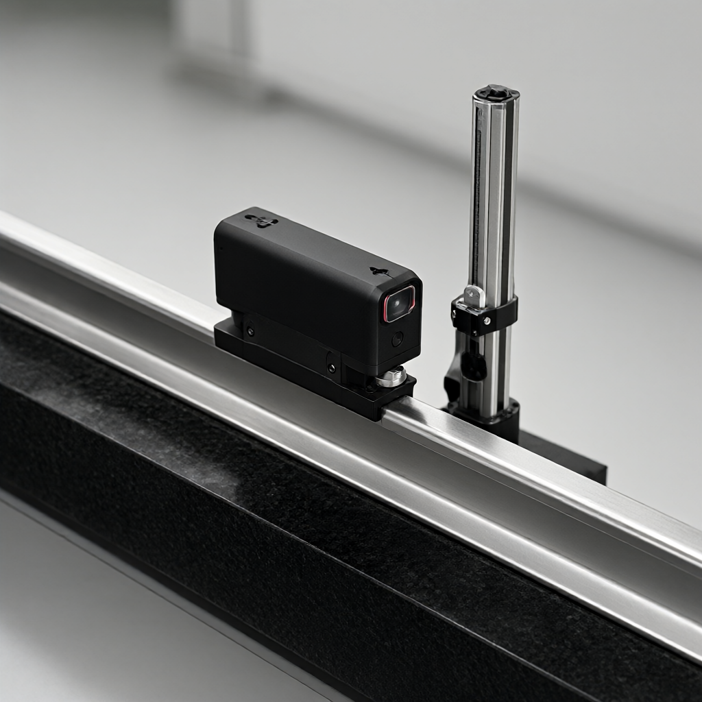
Inspection is a key step in confirming the quality of guide rails. For straightness inspection, high-precision guide rails are usually measured with laser interferometer or air gap level combined with marble platform. The readings should be taken at points along the whole length of the guide rail and the error curve should be drawn. For parallelism inspection, the distance between two reference surfaces can be measured by height gauge or imager.
In addition, the first article inspection must include the full size report, focusing on the straightness, flatness and location of key through holes. It is recommended to carry out full inspection before shipment, especially visual inspection, to confirm that there are no scratches, burrs and oil stains. For batch orders, the supplier shall have a stable inspection system to ensure that the data of each batch of products can be traced.
Frequently Asked Questions (FAQ)
CNC machining aluminum guide rail straightness deviation how to solve?
It is mainly due to internal stress and thermal deformation of the material. It is recommended to increase the aging treatment time before finishing and process in a constant temperature environment. At the same time, optimize the finishing allowance to avoid clamping deformation.
What is the minimum batch size for high-precision rail machining?
This depends on the specific size and process. Usually CNC machining supports 1 piece minimum, but in order to dilute the programming and fixture costs, it is recommended that the batch size be more than 50 pieces to optimize the delivery time and unit price.
How does the surface roughness Ra 0.4μm affect the service life?
Low roughness reduces friction coefficient and wear rate. Ra 0.4μm belongs to fine grinding class, which can significantly improve the running smoothness and life of sliding guide or roller guide.
How to mark straightness tolerance on drawings?
It is necessary to specify the datum plane and the measurement length. For example, label "0.01/1000mm" and indicate which axis or plane the straightness is relative to. Avoid only labeling values without specifying the datum.
Can CNC milling machine guide rails with special-shaped sections?
Yes. Through 4-axis or 5-axis linkage, it is possible to process guide rails with complex cross sections without multiple sets of molds, suitable for personalized customization.
Conclusions and recommendations for action
To control the straightness and parallelism of CNC machining guides, we need to start from three dimensions: material stability, cutting parameter optimization and strict inspection. Choosing suppliers with perfect inspection system and rich experience in precision machining is the key to ensuring the success of the project. If you are looking for CNC machining partners with ±0.01mm precision control capability, support for multiple material customization and stable delivery, welcome to provide your drawings or samples, we will provide you with detailed DFM analysis and technical quotation.



