





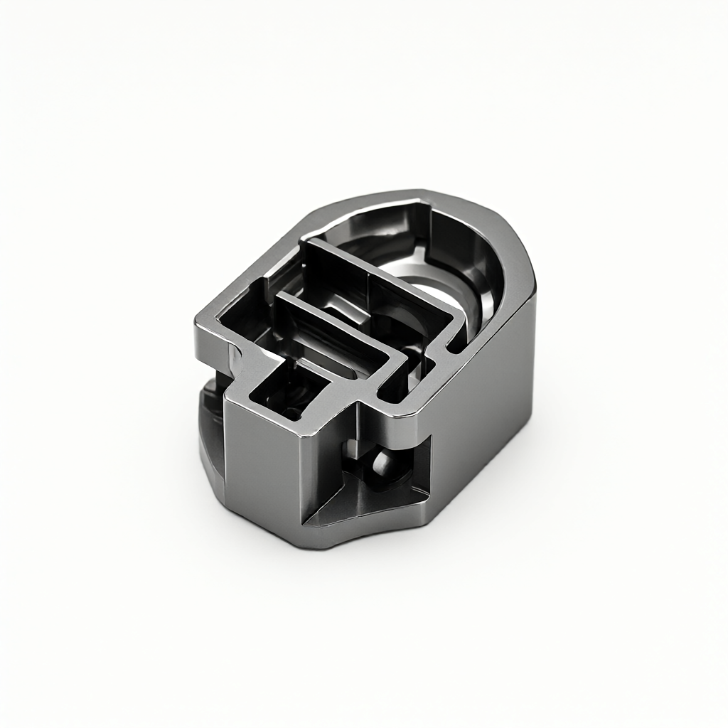
Graphite CNC machining: process logic and factory selection points of EDM conductive parts
in that manufacture of precision conductive part, CNC machining of graphite is the key pre-process for join material blank and EDM workpiece. many engineers pay attention to the precision of final EDM parts, but ignore the machining window of graphite base metal-graphite has low hardness, easy chipping, large dust and anisotropy. if CNC cutting parameters or clamping mode are not appropriate, it will directly lead to surface micro-cracks, size drift and even discharge hole deviation. This paper analyzes the process parameters, clamping strategies and common failure modes of 3-axis and 5-axis graphite milling from the material characteristics, helping technical procurement and R & D personnel to evaluate the technical feasibility of suppliers and judge whether they have the ability to stably process high graphite blanks into conductive substrates that meet EDM requirements.
Influence Mechanism of Graphite Material Properties on CNC Machining
Graphite is not a homogeneous isotropic material. Synthetic graphite (such as isostatic graphite) density is usually 1.70-1.85 g/cm³, resistivity is about 15-25 μΩ·m, thermal conductivity is as high as 200 W/m·K or more. This low hardness (Mohs hardness 3-4) and high brittle coexistence structure determines its cutting mechanism is different from metals:
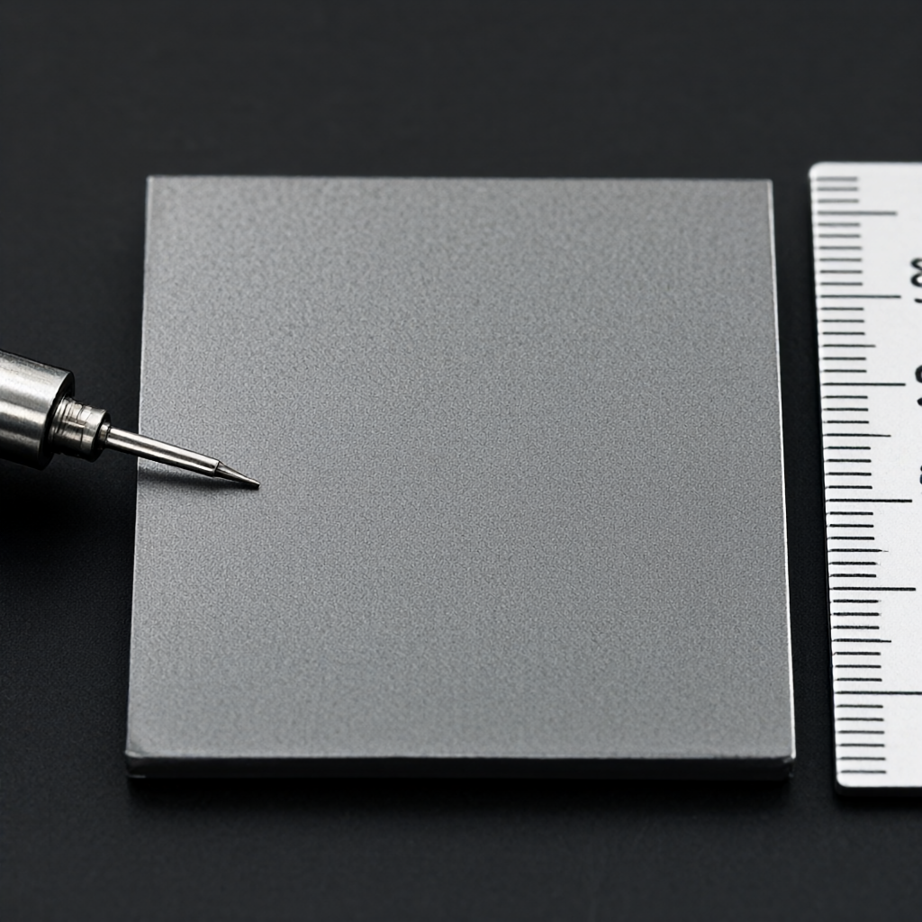
- chipping rather than cuttingGraphite mainly occurs lattice fracture during milling, resulting in a large number of fibrous debris and dust, which is easy to accumulate in chip breaker grooves and chip exhaust spirals.
- thermal sensitivityAlthough graphite has excellent heat resistance, local friction heat will cause thermal stress concentration, initiate microcrack propagation, and affect the flatness of the discharge surface.
- dust hazardGraphite dust fineness can reach micron level, high inhalation risk, and easy to form "mud" wear between machine screw and guide rail, reducing positioning accuracy.
Therefore, the core contradiction of machining graphite CNC workpieces lies in: high speed cutting to improve efficiency, but also to control the depth of cut and feed to prevent edge collapse; both to fully cool lubrication, but also to prevent coolant intrusion into graphite pores resulting in subsequent discharge short circuit risk. In most cases, dry cutting or micro-lubrication (MQL) is better than a large amount of cutting fluid flooding, and it needs to be equipped with a strong dust collection system.
Comparison of 3-axis and 5-axis graphite CNC milling schemes
According to the structural complexity of EDM parts, choose 3-axis or 5-axis linkage machining. The following table compares the advantages and disadvantages of the two schemes in graphite conductive parts:
| dimensionality | 3 axis milling | 5-axis simultaneous milling |
|---|---|---|
| Applicable geometry | Flat electrode, simple step, straight hole array | Irregular curved surface, inclined discharge surface, complex flow channel cooling groove |
| clamping complexity | Low, simple platen or vacuum adsorption | Medium high, multi-station or hydraulic fixture required, torque balance considered |
| accuracy retention | One-sided processing is easy to deform, leaving allowance | One-time clamping to complete multi-surface, uniform reference, small thermal deformation | main risk | Debris clogging, dust contamination of machine tools, commutation errors | Complicated tool path planning, risk of overcutting, thermal drift of machine tools |
| Typical depth/feed | Cutting depth 0.5-2mm, feed 80-150mm/min | Cutting depth 0.3-1mm, feed 50-120mm/min (depending on angle) |
For most electrical discharge machining conductive parts, 3 axes are sufficient to handle flattened electrodes; however, if inclined surfaces or deep cavity cooling channels are involved, 5 axes coaxial machining can avoid reference offset caused by secondary clamping. Selection should be based on drawing tolerance requirements, rather than blindly pursuing the number of axes.
Key process parameters: speed, feed and tool selection
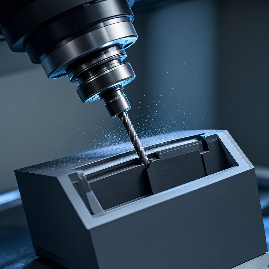
Graphite CNC machining is extremely sensitive to tool wear. Due to the abrasive properties of graphite, carbide inserts are prone to microchipping. Recommended strategies are as follows:
cutting parameter datum
- speed of mainshaft: 10,000-18,000 rpm is recommended. High speed can reduce unit cutting force and reduce chipping.
- feed per tooth: Control in 0.05-0.15 mm/tooth. Avoid large feed to avoid excessive grain tearing.
- depth of cut: Conventional milling 0.5-2 mm; finish milling 0.2-0.5 mm. Rough milling must leave more than 0.5 mm finish machining allowance.
- Tool Material: PVD coated cemented carbide (such as TiAlN) or CVD diamond coating is recommended (only for non-ferrous substrates, graphite processing requires special coatings to prevent diffusion). In most cases, uncoated cemented carbide has a longer life in graphite processing because graphite does not stick to the tool.
clamping and de-stressing
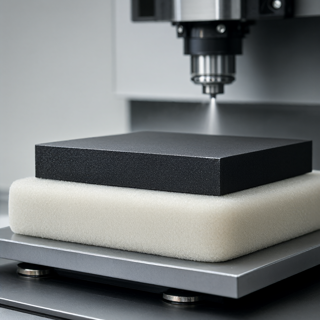
Graphite elastic modulus is low (about 70-90 GPa), easy to plastic deformation. It is recommended to use soft polyurethane cushion with vacuum adsorption or light pressure fixture to avoid stress concentration. Before processing, it needs to stand for 24 hours to eliminate transportation stress. The first piece needs to be "milling-measuring-adjusting-milling" closed loop to compensate clamping deformation.
Common problems and failure avoidance: dust, thermal deformation and discharge surface quality
In actual production, three problems most often lead to batch scrap:
- Dust clogging chip flutes: Graphite chips are fibrous and easy to wind on the cutting edge. Countermeasures: Use short chip blades (2-3 blades), increase the blowing pressure (0.3-0.5 bar), and regularly clean the spindle taper hole.
- Thermal deformation leads to size out-of-tolerance: Although graphite heat conduction is good, but local cutting heat will still cause instantaneous expansion. Countermeasures: adopt "peck deep + empty cooling" strategy to avoid continuous long stroke cutting; monitor the ambient temperature of the machine tool.
- microcrack on discharge surface: Machining residual tensile stress will induce crack propagation in EDM discharge, resulting in uneven electrode burning. Countermeasures: After finishing milling, it is recommended to carry out low temperature stress annealing (depending on the material grade, usually 200-400℃ air cooling), or use wet grinding to remove the surface hardened layer.
Acceptance criteria: How to assess whether graphite CNC machined parts meet discharge requirements
The purchasing or technical team should focus on the following quantitative indicators during acceptance, rather than just visual finish:
- size accuracy: key positioning hole/surface tolerance usually needs to be controlled within ±0.02-0.05mm, discharge gap (gap) related size unilateral allowance needs to be reserved 0.1-0.3mm (depending on EDM parameters).
- surface roughnessDischarge working surface Ra is usually required to be ≤3.2 μm to avoid residual knife marks affecting discharge uniformity; non-working surface has no strict requirements.
- flatness/parallelism: Large-area electrode flatness ≤0.05mm/m, to prevent EDM workpiece and electrode asynchronous withdrawal.
- dust residue: After processing, ultrasonic cleaning or high-pressure air blowing is required to ensure that no graphite powder remains in the cavity or threaded hole, otherwise it will cause short circuit during discharge.
The supplier shall be able to provide the full size inspection report of the first article (CMM coordinate data) and agree on the variation of size within the batch (Cpk≥1.33).
Frequently Asked Questions about Graphite CNC Machining
Is it necessary to use special machine tools for graphite processing?
It is not mandatory, but it must be equipped with an efficient dust removal system. If the ordinary CNC is not equipped with graphite special dust collection (negative pressure ≥15kPa), long-term use will accelerate the wear of the screw and guide rail, and the positioning accuracy will decrease. Factories with cleanliness control or graphite special production lines are more reliable.
Does the discharge surface of graphite after CNC machining need additional polishing?
Generally not required. Graphite itself has self-lubricating properties and high graphitization rate, Ra≤3.2μm after CNC finishing has met most EDM requirements. If the electrode is used for high current density discharge, it can be supplemented with diamond gypsum finishing, but it will increase the cost and process.
How to avoid graphite dust into CNC machine tools?
The key lies in the enclosed cutting area and external centralized dust removal. The cutting area needs to be fully enclosed and protected, the chip exhaust port is connected to an independent dust collector (the filter material needs to be antistatic), and the blowing air path needs to be recycled and filtered. Ask the supplier whether it has the integrated plan of "dry cutting + strong blowing + central dust removal".
What is the minimum feature size for graphite CNC machining?
Depending on tool diameter and machine stiffness. Features with a minimum hole diameter of about 1.5mm can be machined with a 0.5-1.0mm flat bottom tool, and groove widths can be as small as 0.8mm. For finer structures, EDM is recommended for direct machining of blanks rather than CNC premachining.
How long is the lead time for mass production of graphite electrodes?
Depending on the structure complexity and material density. Simple flat electrode, under the premise of sufficient preparation, batch production (100-500 pieces) cycle is usually controllable within 15-25 days, including de-stressing and cleaning. Complex 5-axis special-shaped parts delivery time needs to be extended by 3-5 days for tool path verification and first piece trial cutting.
Conclusions and recommendations for action
Graphite CNC machining is the cornerstone of discharge part quality. When selecting suppliers, focus on whether they have graphite dedicated dust removal system, first article full size inspection capability and batch consistency control data. If you are facing size drift or discharge surface cracks of conductive graphite parts, it is recommended to send drawings and tolerance requirements to professional processors for DFM (design for manufacturability) feedback and accurate quotation based on their equipment capabilities to avoid trial and error costs.



