





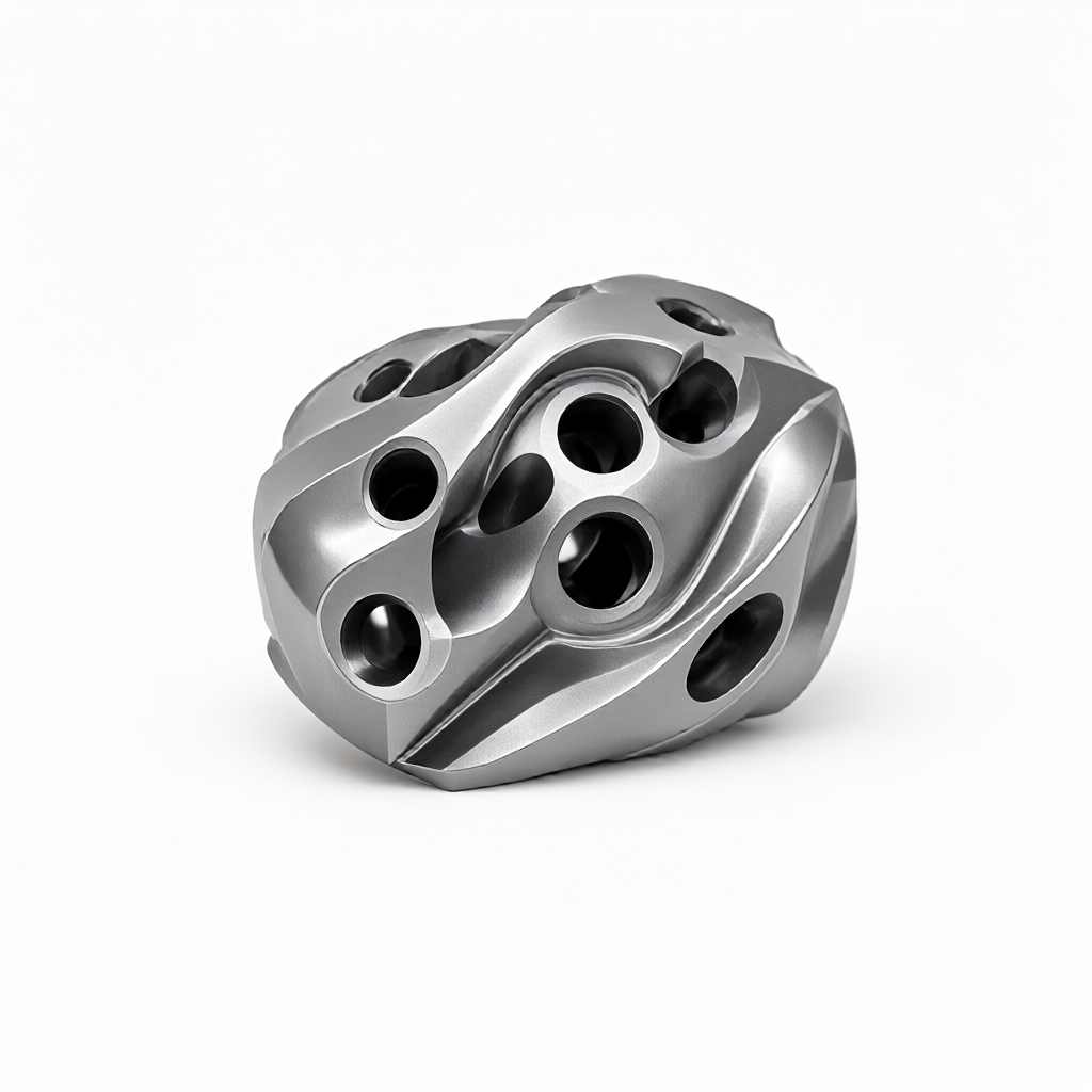
Entry points for five-axis CNC machining of turbomachinery parts: from rigidity to spindle
In the field of turbine machinery such as aeroengine blades, gas turbine impellers and precision pump valves,Five-axis CNC machiningIt is the core path to solve complex surfaces. However, many engineers and purchasers are prone to fall into the misunderstanding when inquiring: only looking at the five-axis function of the machine tool, ignoring the deep influence of dynamic stiffness analysis and spindle selection on surface quality. Based on ShowyMetal's mass production experience on 72 CNC machine clusters, this paper deeply analyzes how to ensure the size accuracy and batch consistency of ±0.01mm under the high finish requirement of Ra0.4μm through dynamic rigidity evaluation and accurate spindle selection.
Dynamic stiffness challenges in machining turbomachinery parts
Turbomachinery parts are usually made of titanium alloys (such as Ti-6Al-4V), superalloys, or precision stainless steels, which are rigid, have poor thermal conductivity, and are prone to vibration during cutting. Traditional static stiffness indicators (such as machine tool table stiffness) cannot fully predict surface quality under high speed cutting.
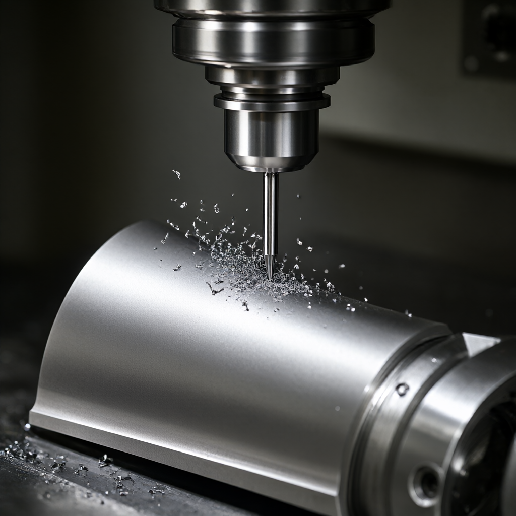
- Dynamic modal analysis:We need to identify the natural frequency of the machine-workpiece-tool system. If the spindle rotates near this frequency, resonance will occur, resulting in an increase in the depth of the cut, and even micro-chipping.
- Deformation of thin-walled parts:Turbine blades or impellers are often very thin, and the transient deformation caused by cutting forces may exceed the tolerance band of ± 0.01 mm. Machine tools with insufficient dynamic stiffness will lead to "tool yield" effect, resulting in size drift.
For buyers, it is more critical to confirm whether the supplier has the ability to simulate cutting based on FEM (Finite Element Analysis) than simply asking "can you do it?". This directly determines the first part yield and batch stability.
Decisive influence of spindle selection on machining accuracy
Spindle is the heart of the five-axis machine tool, its thermal elongation characteristics and natural frequency directly determine the machining limit. In the finishing stage of turbomachinery parts, spindle selection should focus on the following parameters:
Temperature Rise Control of High Speed Spindle
High-speed machining (Spindle Speed > 24,000 RPM) produces significant thermal effects. Normal air-cooled or oil-cooled spindles have thermal stability times of up to 4-6 hours, while turbine wheel machining often needs to be completed in short batches. ShowyMetal uses a constant temperature oil-cooled spindle that can control thermal elongation to within 5μm, effectively compensating for size drift.
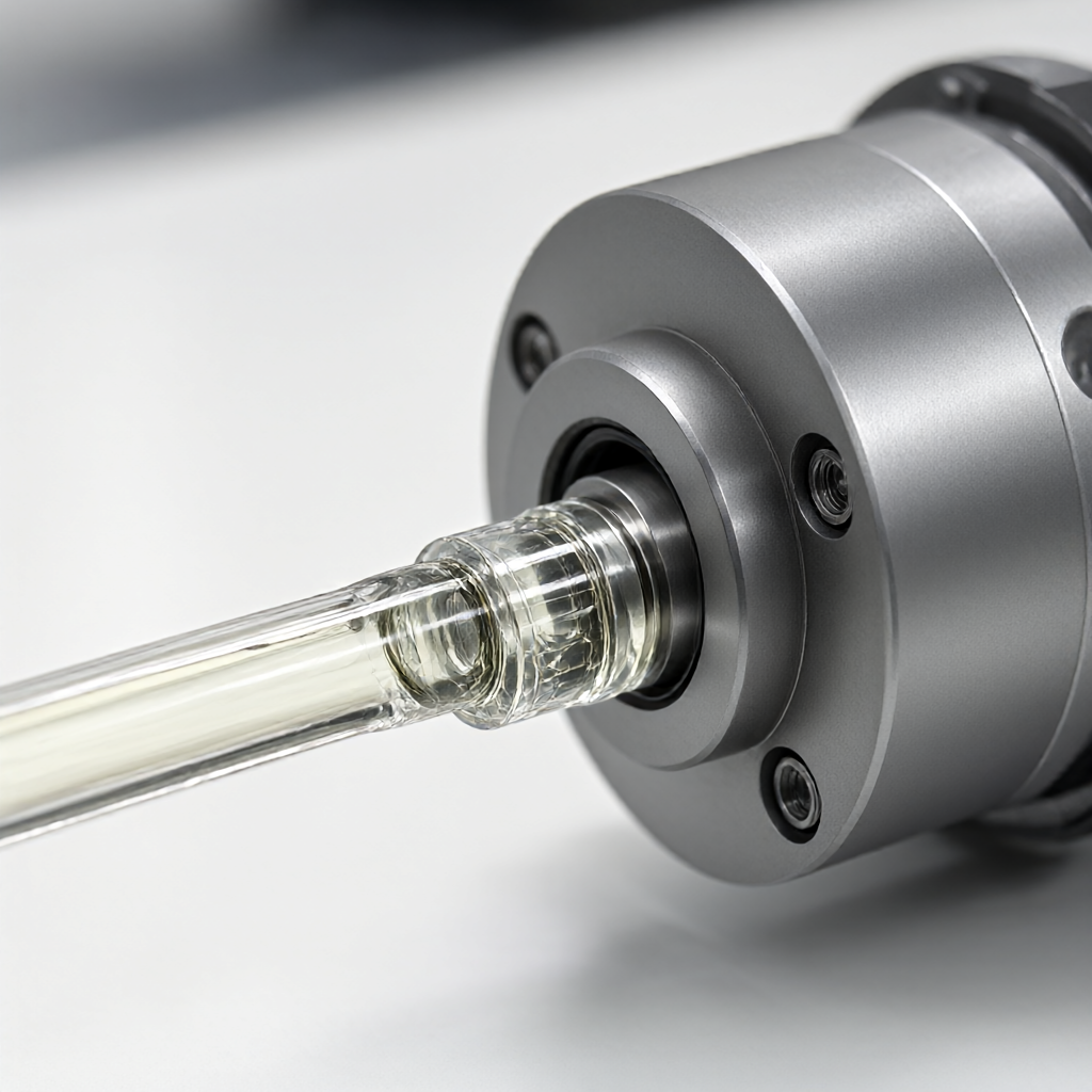
Natural frequency and resonance avoidance
The natural frequency of the workpiece should be avoided when selecting. If the natural frequency of the spindle is too low (e.g. less than 100 Hz), it is easy to excite vibration at high feed rates. For thin-walled turbine parts, it is recommended to select a spindle with a natural frequency> 200 Hz, and cooperate with a high rigid tool holder system to ensure track smoothness when 3-axis/5-axis linkage.
Comparison of different spindle configuration schemes and applicable scenarios
According to the batch and precision requirements of turbomachinery parts, we compare two mainstream spindle configuration solutions for engineering selection:
| Compare Dimensions | High Speed Electric Spindle (Direct Drive) | Belt/Shaft Drive |
|---|---|---|
| maximum speed of revolution | 20,000 - 40,000 RPM | usual< 12,000 RPM |
| Applicable processing type | Finish machining, drilling, milling small diameter cavities (Ra0.4-0.8μm) | Rough machining, large diameter end face, high strength material removal |
| thermal stability | Need to cooperate with constant temperature system, thermal deformation is small | Large thermal deformation, need a long time constant temperature |
| dynamic stiffness | High, suitable for thin-walled parts | Extremely high, suitable for rough machining with high anti-vibration requirements |
| batch consistency | High, less affected by temperature | Medium, frequent calibration of thermal elongation required |
Engineering recommendations:For high-precision batch parts such as turbine wheels, a strategy of "coarse and fine separation" is recommended: rapid material removal using a mechanical spindle or high-power spindle, followed by a high-speed electric spindle for final finishing. This strategy retains the advantages of dynamic rigidity while ensuring surface finish.
Optimization of 5-axis tool path from DFM angle
Excellent dynamic rigidity comes not only from the machine tool, but also from the tool path strategy. When machining turbomachinery parts in 5 axes, ShowyMetal's engineering team optimizes the following conditions through DFM (Design for Manufacturability) review:
- Axial feed limit:In thin-walled areas, limit the axial depth of the tool to avoid deformation caused by local stress concentration. For example, control the Z-axis feed step within 0.1mm.
- Spindle angle optimization:Avoid collision between tool and machine column, while keeping spindle axis in a better rigid range (usually between 30°-60° swing angle).
- Empty stroke separation:5-axis linkage function is used to optimize idle stroke, shorten non-cutting time and reduce thermal drift accumulation at low speed.
The interference between tool path and machine kinematics can be verified by simulation software, and the machining error can be controlled within the theoretical range. This pre-engineering analysis is the key to avoid "scratch" or "size out of tolerance" in mass production.
Acceptance criteria: How to determine whether dynamic rigidity meets the standard
As purchaser, upon receipt of turbomachinery parts, in addition to the conventional size report (CMM report), the supplier shall be required to provide the following dynamic process-based inspection data:
- Surface roughness distribution:The Ra requirement of 0.4 μm means that the peak-to-valley difference needs to be strictly controlled.
- Geometric tolerance analysis:For impellers, focus on flatness and concentricity. Insufficient dynamic stiffness often manifests as edge warpage, and the tolerance tolerance rate of shape and position is significantly higher than that of ordinary parts.
- Microscopic metallographic examination:For superalloy parts, check the kerf surface for microcracks or plastic rheological layers, which are traces of cutting heat and dynamic vibration.
ShowyMetal is equipped with coordinate measuring machines, optical measurement and roughness meters, and can issue ISO 9001-compliant quality reports according to 100% full inspection or AQL standards, ensuring that every turbomachinery part delivered can withstand dynamic rigid viewing.
Frequently Asked Questions
How to balance efficiency and dynamic rigidity when machining turbine parts with five-axis CNC?
The strategy of "coarse and fine separation" is usually adopted. Efficiency is preferred in roughing stage, using large diameter tools and lower rotation speed; rigidity is preferred in finishing stage, increasing spindle rotation speed to more than 20,000 RPM and reducing cutting depth to 0.1-0.2mm to suppress vibration.
What are the consequences of thermal elongation of main shaft in titanium alloy turbine blade machining?
Thermal elongation can cause Z-axis size drift, typically between 10-20μm. Failure to perform thermostatic control or compensation can result in blade thickness over-tolerance or insufficient leading edge thickness. It is recommended that the supplier have thermal error online compensation or a constant temperature workshop environment.
How to ensure consistent appearance (no scratches) in mass production of turbomachinery parts?
The key lies in tool holder dynamic balance (G0.25 grade or less) and tool clearance optimization. ShowyMetal strictly implements first article verification and process inspection in mass production, and eliminates defects through 100% full inspection to ensure high gloss and scratch free appearance quality.
Is it possible to machine turbine hubs using turn-milling compound instead of five-axis milling?
For symmetrical hub parts, turn-milling compound is efficient and rigid. However, complex asymmetric blade surfaces still rely on five-axis milling. ShowyMetal has turn-milling compound and five-axis machining centers to select the most economical process route according to the geometric characteristics of the part.
What parameters are required for inquiry besides drawings?
It is recommended to provide material designation (e.g. Inconel 718, Ti-64), batch quantity, target tolerance (e.g. ±0.01mm), surface roughness (e.g. Ra0.4μm) and surface treatment requirements (e.g. anodization). This information helps suppliers to quickly assess dynamic stiffness risks and give accurate delivery dates.
Conclusion and Call to Action
5-axis CNC machining of turbomachinery parts is not only a stack of machine parameters, but also a system engineering of dynamic stiffness analysis, spindle selection and tool path optimization. ShowyMetal relies on the cluster advantage of 72 CNC machines and rich engineering experience to provide precision parts with high finish and batch consistency within 15-25 days.If you are looking for a partner who can solve the deformation problems of complex surfaces and thin-walled parts, please send us your CAD drawings and detailed technical requirements. Our engineering team will provide DFM suggestions and quotations based on dynamic stiffness evaluation within 24 hours.



