





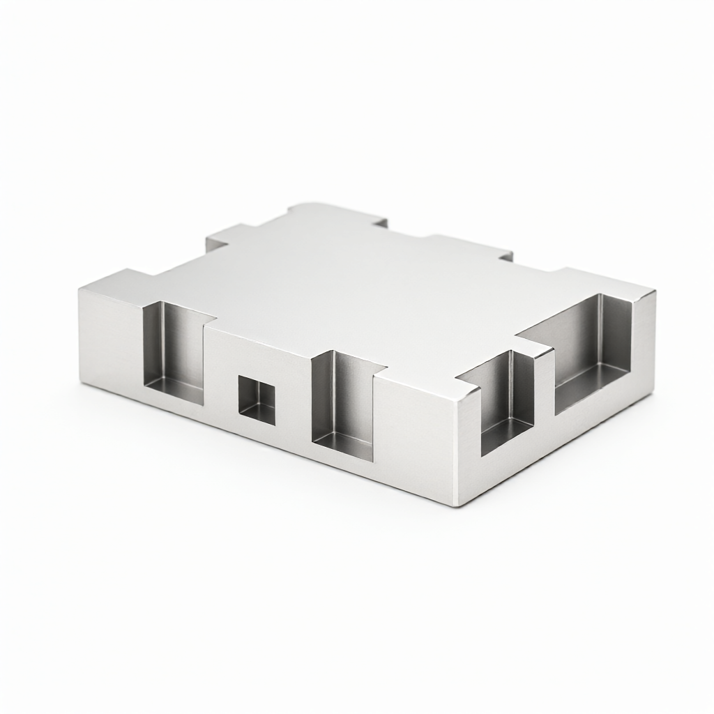
In the field of precision electronics and power equipment,Aluminum alloy CNC milling heat sinkIt is the core component to control thermal management efficiency. Facing the high temperature challenges of 5G base stations, high-power lasers and new energy vehicle electronic control units, relying solely on high thermal conductivity materials is not enough to solve local hot spots. In this paper, the thermal conductivity characteristics of 6061 and 7075 aluminum alloys are analyzed in depth, combined with 5-axis milling process and air duct structure optimization, to provide a reference scheme with engineering executability for heat sink selection and mass production.
Physical Effect of Aluminum Alloy Grade on Heat Dissipation Performance
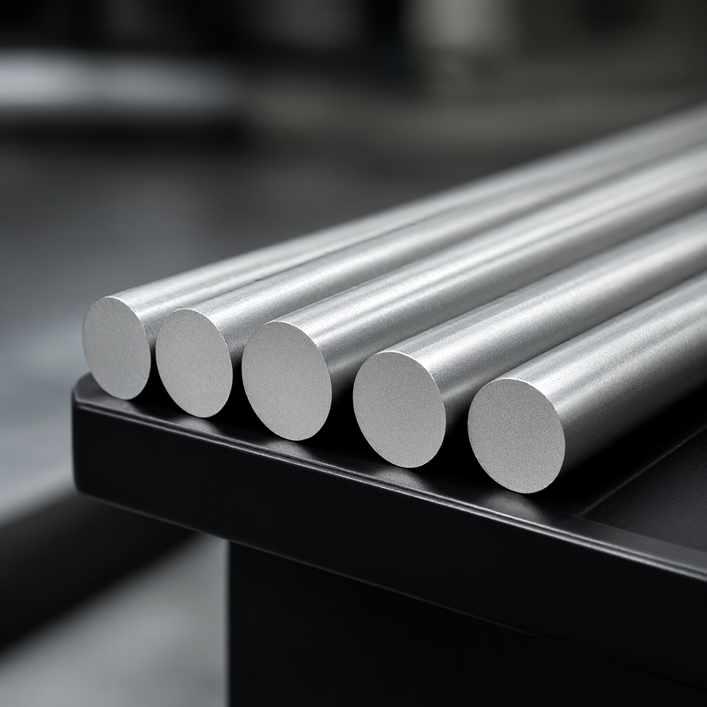
The substrate selection of heat sinks directly determines the benchmark efficiency of heat conduction. In industrial CNC machining, aluminum and aluminum alloys dominate due to their lightweight and easy processing characteristics, but the thermal conductivity of different grades varies significantly, and it is necessary to match the heat dissipation power and ambient temperature.
Comparison of thermal conductivity and mechanical properties of common brands
- 6061-T6 aluminum alloy: thermal conductivity of about 150-180 W/(m·K), yield strength of about 275 MPa. Its advantages are good processability, excellent weldability, and excellent adhesion of anodic oxide film, which is the first choice for general heat dissipation structures. Most consumer electronics and communication equipment heat sinks use this material.
- 7075-T6 aluminum alloy: Thermal conductivity is about 130-150 W/(m·K), yield strength is up to 500 MPa. Although the thermal conductivity is slightly lower than 6061, its specific strength (strength/density ratio) is extremely high, suitable for high strength heat dissipation brackets with limited space and high mechanical stress.
- Aluminum 1050/1100Thermal conductivity exceeds 200 W/(m·K), excellent thermal conductivity, but low mechanical strength, need to increase wall thickness or auxiliary structure, mainly used in high-power laser water-cooled head connectors that are insensitive to weight but extremely strict on thermal resistance.
engineering advice: 6061-T6 is preferred if structural support and heat dissipation are required; pure aluminum or 6101 alloy is preferred if excellent thermal conductivity is sought and the structure is already carried by other components. State (e.g. T6 or H112) is clearly indicated when inquiring, because heat treatment state directly affects final thermal conductivity.
Thermodynamic principles for fin structure design
High-performance heat dissipation is not simply stacked aluminum. The core of fin design is to balance thermal resistance and fluid resistance. Structural design errors can lead to "heat bottleneck" appearing in the flow path rather than the conduction path.
Definition of key geometric parameters
- fin pitch: Usually set to 6 - 10 mm. Too dense spacing will hinder airflow turbulence and increase friction resistance, resulting in a decrease in air volume; too wide spacing will form a boundary layer on the surface of the fins, reducing convective heat transfer coefficient.
- fin thicknessCNC milling can be stable processing to 0.5 - 1.0 mm. Increased thickness helps reduce thermal resistance along the way, but too thick will lead to poor cooling effect at the top of the fin, and increase material consumption and weight.
- matrix thickness: It is suggested that ≥ 2 mm. The matrix is the main heat conduction path, and its thickness should meet the temperature rise requirements under steady heat flux density. It is usually estimated by the formula $T_{max}-T_{amb}= qL/k $, where $L $is the thickness of the matrix and $k $is the thermal conductivity.
For complex curved surfaces or special-shaped heat dissipation modules,microchannel designThe heat exchange area can be significantly improved, but the chip space of CNC tool needs to be evaluated to avoid short circuit caused by residual aluminum chips on the inner wall of the microchannel or affecting convection.
Precision CNC milling technology determines the heat dissipation quality
Design drawings cannot directly determine the performance of finished products, and the stability of processing directly determines the thermal conductivity and reliability of heat sinks. In mass production, the consistency of process parameters is crucial.
5-axis linkage and tool path optimization
For heat sinks with complex surfaces or inclined fins, 5-axis CNC machining avoids deformation caused by tool lateral forces and maintains fin angle consistency. The following principles should be followed during machining:
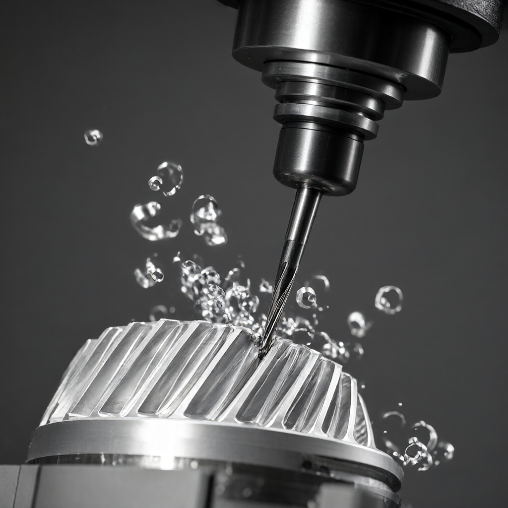
- tool selection: The use of cemented carbide end mills, the cutting edge needs to be coated (such as TiAlN) to reduce friction heat, reduce local temperature rise in the processing area, and prevent aluminum alloy from affecting surface finish due to high temperature oxidation.
- cutting parameters: 6061 aluminum alloy in dry cutting or air-cooled conditions, cutting speed Vc is recommended to be set to 300 - 500 m/min. Too high cutting speed will reduce the thermal conductivity of aluminum alloy due to friction heat (about 5%-10%).
- roughness control: The roughness Ra of the radiating surface shall be controlled within 3.2-6.3 μm. The surface is too smooth (such as Ra<0.8 μm)虽然降低了传导热阻,但会增加光线反射并可能降低流体湍流,反而不利于对流换热。粗糙度的微小起伏有助于打破层流边界层。
machine stress relief: The residual internal stress after CNC milling can cause the parts to deform slightly during subsequent use or temperature change, especially for thin-walled heat sinks. It is recommended to carry out aging treatment or vibration aging after rough machining, and then finish machining to ensure size stability. The tolerance is recommended to be controlled within ±0.01 mm.
Matching Analysis of Material Grade and Processing Technology
Different grades of aluminum alloy in CNC machining behavior differences, a direct impact on the heat sink batch consistency and cost. The following is a technical comparison of the two mainstream programs:
| Compare Dimensions | 6061-T6 MILLED HEAT SINK | 7075-T6 Milling Heat Sink |
|---|---|---|
| heat conductivity coefficient | About 1 70 W/(m·K), excellent thermal conductivity | Approx. 140 W/(m·K), thermal resistance slightly higher than 6061 |
| mechanical strength | Medium, suitable for general structural support | Extremely high for high pressure loads and high vibration resistance |
| processability | the cut resistance is small, that edge is not easy to break, the service life of the cutter is long, and the cut is suitable for mass production | High hardness, cutting heat, easy to produce build-up tumor, need to reduce the feed speed, low processing efficiency |
| surface treatment | the anodic oxidation effect is excellent, and that film lay is uniform and compact | Anodic oxidation black spot or color difference is easy to occur, and sandblasting + electrophoresis or natural color hard film treatment is usually adopted. |
| applicable scenarios | 5G base station, communication equipment, general PCB board heat dissipation | Robot joints, high temperature and high vibration environment around automobile engines |
The 6061-T6 has a lower tool wear rate than the 7075. The 6061-T6 is cost-effective for standard heat sinks. The 7075's high fatigue resistance is a necessary investment if the product is to operate in an automotive OEM environment and must withstand severe vibration and high temperature cycles. It is recommended to lock the material at the DFM (Design for Manufacturing) stage to avoid scrap due to later processing deformation.
Change of Heat Dissipation Performance after Surface Treatment and Avoidance Strategy
Surface treatment is standard for custom aluminum heat sinks, but certain processes can significantly alter thermal conductivity. The wrong post-treatment choice may offset the effect of the heat sink design.
Thermal Resistance Effects of Common Surface Treatments
- anodize: The oxide film itself is an insulator (thermal resistance of the order of $10^{-4}$ K·m²/W), and the thickness is usually controlled at 10-30 μm. This thermal resistance is negligible for electron heat dissipation. However,sealing processCrucially important, if improperly sealed resulting in residual internal porous structure, the oxide film will absorb moisture and peel off under high temperature and humidity conditions, resulting in heat dissipation surface failure. Boiling water resistant sealing process must be specified.
- Electroplating (e.g. nickel plating, chromium plating): The thermal conductivity of metal coating is high, but the porosity and bonding strength of plating layer are the key. Thin layer plating (<5 μm)对散热影响较小,但镀层若出现裂纹,在热循环下易剥落,造成散热面粗糙度急剧恶化。
- Paint/powder coating: Thermal resistance is much higher than oxide film and plating film. If heat dissipation area is limited and coating must be used, increase fin density or reduce heat flux density, otherwise junction temperature will be significantly increased.
For high finish and flawless requirements,Sandblasting + AnodizingThe combination of can provide both beautiful and weather resistant surface. In mass production, it is necessary to establish the appearance inspection standard (AQL 2.5), focusing on the uniformity of the oxide film to ensure that the heat dissipation surface and the installation surface are consistent, meeting the strict appearance specifications of consumer electronics customers.
Quality inspection and batch consistency control
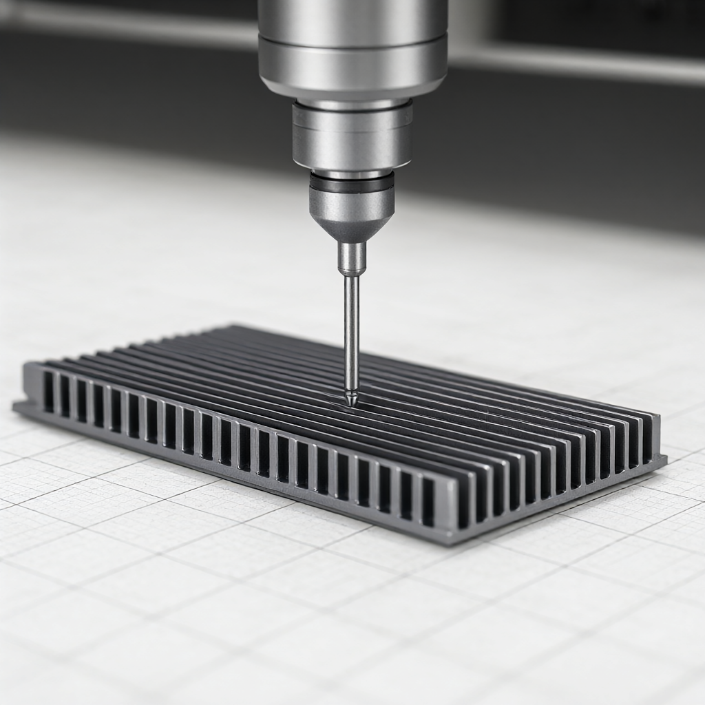
Although the heat sink is not a load-bearing core component, the thermal failure risk has a great impact on the system reliability. In addition to the conventional size inspection (CMM coordinates), it is necessary to add a sampling scheme for thermal conductivity.
Key test items and standards
- thermal resistance test: Use laser flash method or steady-state heat flow meter to conduct sampling inspection on ≥3 pieces of each batch to verify whether the thermal conductivity reaches more than 95% of the theoretical value of the brand (eliminate the influence of internal pores).
- interfacial bonding strength: If the heat sink needs to be attached by thermal interface material (TIM), the bonding strength between the aluminum alloy substrate and the machined surface shall be tested to prevent micro-air gap after TIM application.
- heat cycle test: Simulate extreme working conditions, such as 1000 cycles between-40℃ and +85℃, and detect whether there is microcrack at the root of fin, which is a direct reflection of insufficient stress release or brittle fracture of material.
In mass production, since the wear of milling cutter will cause the fin size to slightly increase (e.g. 0.02 mm), it is recommended to introduce the cutter wear compensation mechanism into the machining procedure, and perform self-test range confirmation once every 100 pieces to ensure that the fin spacing error is controlled within ±0.05 mm and maintain the consistency between batches.
Aluminum alloy CNC milling heat sink better material must be 6061?
Not necessarily. 6061 is a popular choice for communication heat sinks because it offers a good balance between heat conduction and cost. However, 7075 is more suitable for robotic joints with very high mechanical loads (e.g., multiple times of gravity) or requiring excellent specific strength. For short heat dissipation paths and extremely sensitive to thermal resistance (e.g., semiconductor lasers), pure aluminum (1050) or 6101 alloy are preferred. Material selection must be calculated in combination with structural loads and heat flux.
Can 5-axis machining significantly reduce the thermal resistance of heat sinks?
5-axis machining itself does not change the thermal conductivity of the material, but by optimizing the tool axis direction and feed path, it can greatly reduce the aluminum scrap residue and tool friction heat, and maintain the microstructure integrity of the machined surface. For the heat sink with micropores or complex flow channels, 5-axis machining can produce micro-nano structures that cannot be realized by 3-axis machining, increasing the heat exchange area, thus reducing the overall system thermal resistance from the structural level, rather than the material thermal resistance.
How to evaluate the influence of CNC heat sink machining accuracy on the heat dissipation effect?
Two main considerations: Fin spacing error and flatness. Fin spacing deviation of more than ±0.1 mm will lead to local blockage of air duct, air volume decreased, the convective heat transfer coefficient may be reduced by 5%-10%. Flatness if the error is greater than 0.05 mm, resulting in uneven assembly gap, TIM (silicone grease) can not be evenly filled, the interfacial thermal resistance will rise sharply. Therefore, CNC machining flatness is recommended to control within 0.02 mm.
How to solve the problem of anodizing color difference when mass producing heat sinks?
The color difference comes from the control of impurity content and oxidation current density of aluminum alloy. The supplier shall be appointed to use high purity aluminum ingot (total impurity content<0.1%),并在阳极氧化槽内使用温度控制精度±1℃的纯水系统。对于批量件,务必要求供应商提供同批次氧化对比样板,执行首件确认制,并在每批次中增加10%的色卡抽检比例,避免整批货物因外观不一致导致退货。
Can residual surface stresses cause size springback after heat sink processing?
Very well. Yeah. CNC milling can leave residual tensile stresses in the surface layer, especially in thin-walled areas, which may warp 0.01-0.02 mm after a period of time. To ensure long-term size stability, it is recommended that precision heat sinks Add a cold treatment (-80℃ cryogenic) or vibratory stress relief process (especially for optical modules or semiconductor packages) to relieve stress. If the part is complex and demanding, a 0.02 mm trim allowance or sufficient age stabilization should be achieved prior to CNC finishing.
The design of heat sink is ultimately determined by the consistency of thermal resistance data, appearance specifications and mass production. Aluminum alloy CNC milling technology provides a reliable manufacturing foundation for complex thermal management structures. For specific heat dissipation application scenarios, it is recommended to submit detailed drawings and technical specifications after defining material designation, surface treatment process and tolerance requirements in combination with thermal fluid simulation results. By providing quantifiable DFM recommendations and quick quote responses, the lead time from R & D to production validation can be significantly reduced, reducing the risk of thermal failure of the cooling system.



