





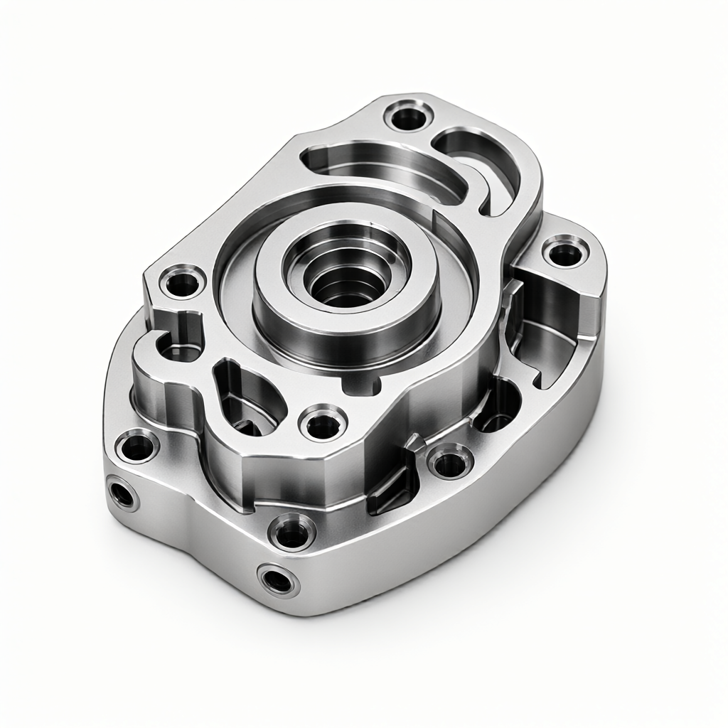
CNC machining tolerance setting: ±0.01mm core principle of practical operation
In precision CNC parts customization, controlling the size tolerance to ±0.01mm is a key requirement for aerospace, medical equipment and high-end automation equipment. However, the tighter the tolerance setting is, the better. It must be comprehensively evaluated in combination with material characteristics, process paths and inspection methods. For engineers and purchasers, understanding the actual constraints of ±0.01mm tolerance can effectively avoid communication barriers between design and manufacturing, reduce trial and error costs, and ensure consistency in mass production. ShowyMetal provides precision CNC machining services covering 3/4/5 axis milling, turning and milling compound processes, supporting aluminum, steel, stainless steel and engineering plastics, etc., with accuracy up to ±0.01mm, surface finish Ra0.4μm, and equipped with full size detection capabilities such as three-coordinate and optical measurement, providing reliable landing solutions for high precision tolerance requirements.
Key Factors Affecting ±0.01mm Tolerance Realization
To achieve a tolerance band of ±0.01mm, it is first necessary to clarify that the accuracy level usually corresponds to ISO 286 IT5-IT6. This accuracy is not solely dependent on the machine brand, but is determined by "machine accuracy + tool compensation + material characteristics + thermal deformation control".
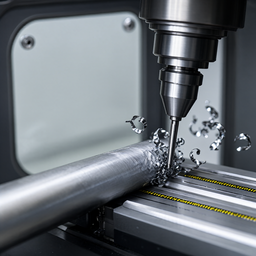
- Rigid guide rail of machine toolHigh-precision multi-axis machining center needs to have stable linear guide and ball screw preload, usually requires positioning accuracy within ±0.005mm, as the basis for subsequent micron-level machining.
- Tool Wear and Compensation: When milling aluminum or stainless steel, tool edge wear will directly lead to size drift. It is necessary to dynamically update the tool compensation value through online tool length measurement or periodic optical measurement to ensure consistent machining allowance.
- thermal stability: Aluminum linear expansion coefficient is high, cutting heat in processing is easy to cause trace deformation of the workpiece. It is necessary to optimize the cutting parameters (reduce feed, increase coolant), or finish machining and testing in the constant temperature workshop (20±1℃) to eliminate the influence of thermal drift.
- clamping deformation control: For thin-walled parts or slender shafts, rigid clamping easily leads to elastic deformation and springback after loosening. Vacuum chuck, soft claw or precision tooling should be used to minimize clamping stress.
±0.01mm Tolerance Process adaptation on different materials
Different materials have different responses to chip morphology, cutting force and heat, and process parameters need to be adjusted accordingly, otherwise it is difficult to achieve ±0.01mm tolerance stably.
- Aluminum alloy (such as 6061-T6, 7075-T6): Good cutting performance, but easy to stick tool. It is recommended to use small knife diameter (≤3mm), high speed (8000-12000 rpm) milling, keep sharp edge; finishing allowance control in 0.05-0.1mm.
- Stainless steel (such as 303, 316L): High tensile strength, poor thermal conductivity, easy to produce work hardening. Need to use large rake angle tools, reduce feed rate, increase cutting fluid flow to dissipate heat; avoid intermittent cutting, prevent tool chipping.
- Titanium alloy (such as Ti-6Al-4V): High chemical activity, easy to diffuse wear with tools at high temperatures. Need to significantly reduce cutting speed, use cemented carbide or CBN tools, and strengthen cooling; fine turning/fine milling allowance needs to be reserved for more than 0.1mm.
- Engineering plastics (such as POM, PEEK): Low hardness, easy to burr. To avoid high speed cutting lead to fusion bump, use large clearance angle, negative rake angle sharp tools;POM size stability is good, but PEEK needs to strictly control the machining allowance to prevent thermal deformation.
Comparison between precision CNC machining tolerance and conventional tolerance scheme
| accuracy class | Typical Tolerance Zone (mm) | applicable process | detection means | Batch Consistency Difficulty | applicable scenarios |
|---|---|---|---|---|---|
| conventional tolerance | ±0.1 ~ ±0.2 | 3-axis rough milling/ordinary turning | Calipers/micrometers | low | Structural support, housing |
| higher tolerance | ±0.05 | Finish milling/turning | Vernier Calipers/Projectors | centre | Standard shaft parts, gear blanks |
| Multi-axis linkage turning-milling compound/walking machine | CMM/Optical | tall | Aeronautical structures, medical implants |
The ±0.01mm tolerance scheme requires extremely high equipment state stability, operator skills and inspection frequency. If the design drawings do not specify tolerances, it is recommended that engineers mark ±0.05 or ±0.02 on critical mating surfaces instead of blindly marking ±0.01 to balance manufacturing costs and assembly performance.
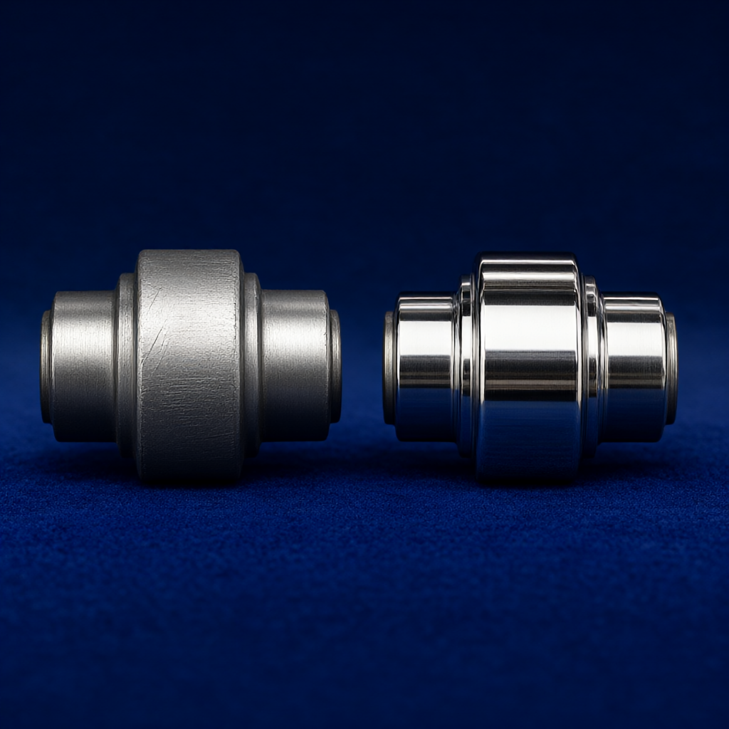
±0.01mm Tolerance Practical Operation Points and Inspection Specifications
To achieve ±0.01mm in mass production, closed-loop control from the first piece to the full inspection must be established.
- First Article Validation (FAI): The first piece shall be tested by CMM for full size, and Cpk report shall be issued. The Cpk value shall be ≥1.33 before mass production is approved, so as to ensure that the process capability meets the tolerance requirements.
- process inspection1-2 pieces shall be sampled every 2 hours, and the micrometer or pneumatic measuring tool shall be used to measure the critical hole diameter/shaft diameter; if the size of 3 consecutive pieces deviates in one direction, the machine shall be stopped immediately to check the tool wear or thermal deformation.
- Full inspection of shipment: Perform 100% full size inspection on ±0.01mm critical size, retain measurement data, ensure consistent size of each batch of parts, and reduce customer assembly risk.
- Surface finish control: ±0.01mm tolerance is often accompanied by Ra0.4μm or even lower finish requirements. Precision cutting + polishing or honing process is required to avoid the ripple marks left by tool vibration affecting surface quality.
Common Failure Modes and Avoidances of High Precision CNC Tolerance Setting
- tool chipping: mostly occurs in stainless steel/titanium alloy finish machining, resulting in instantaneous size out of tolerance. Avoidance: reduce feed rate, use diamond-rich coated tools, check tool radius with micrometer before finish machining.
- hot deformation springback: After finishing, the workpiece is not cooled in time and the size is too small; after cooling, the size is too large. Avoidance: After finishing, place it in the constant temperature zone for ≥30 minutes and then detect, or use a non-contact laser probe.
- clamping residual stress: Thin-walled parts release after clamping, ovality deformation. Avoidance: three-point vacuum adsorption or customized elastic tooling to avoid local high pressure.
FAQ
CNC machining tolerance ±0.01mm How to maintain consistency in mass production?
It is necessary to establish a tool life monitoring mechanism to dynamically compensate tool compensation according to blade length wear; 100% full size detection shall be implemented for key size, and the stability of equipment shall be verified by process capability analysis with Cpk≥1.33.
Which materials are most suitable for ±0.01mm tolerance?
Aluminum alloy (6061/7075) and 303 stainless steel have good cutting stability and high size consistency; titanium alloy and PEEK need strict control of thermal deformation, and it is recommended to keep sufficient finishing allowance and test under constant temperature environment.
What equipment is needed to detect ±0.01mm tolerance?
CMM (coordinate measuring machine), pneumatic measuring instrument or high-precision optical projector shall be used for critical size; roughness meter shall be used to verify Ra value; all measuring instruments shall be calibrated regularly to ensure that the measurement error is far less than the tolerance zone width.
Does tolerance marking ±0.01mm increase manufacturing costs?
Yes. Compared with ±0.1mm, the machining allowance is reduced, the cutting speed is reduced, and the inspection frequency is increased, resulting in an increase in single man-hour and equipment occupancy. It is recommended that only the key functional surfaces be marked, and the non-mating surfaces be relaxed to ±0.1mm to optimize the cost.
How does ShowyMetal support precision tolerance customization?
ShowyMetal provides 3/4/5 axis milling, turning and milling compound and machining, with accuracy up to ±0.01mm, Ra0.4μm; equipped with CMM and optical measurement system, perform 100% full inspection of first article confirmation and shipment; support DFM recommendations, optimize tolerance allocation at the design end, ensure batch 15-25 days delivery and appearance quality consistency.
conclusion
Tolerance setting of ±0.01mm is a trinity system engineering of material, process and inspection. Engineers shall combine material thermal stability, machine tool accuracy and assembly function requirements when marking tolerances to avoid blindly pursuing limit tolerances; purchasers shall clarify key size inspection methods and process capability requirements when docking with suppliers to reduce batch consistency risks. If your project involves precision fits, high finish or special-shaped surfaces, you can send the drawings and bill of materials to the ShowyMetal engineering team to obtain DFM recommendations and tolerance feasibility assessments to ensure accurate implementation from proofing to mass production.



