





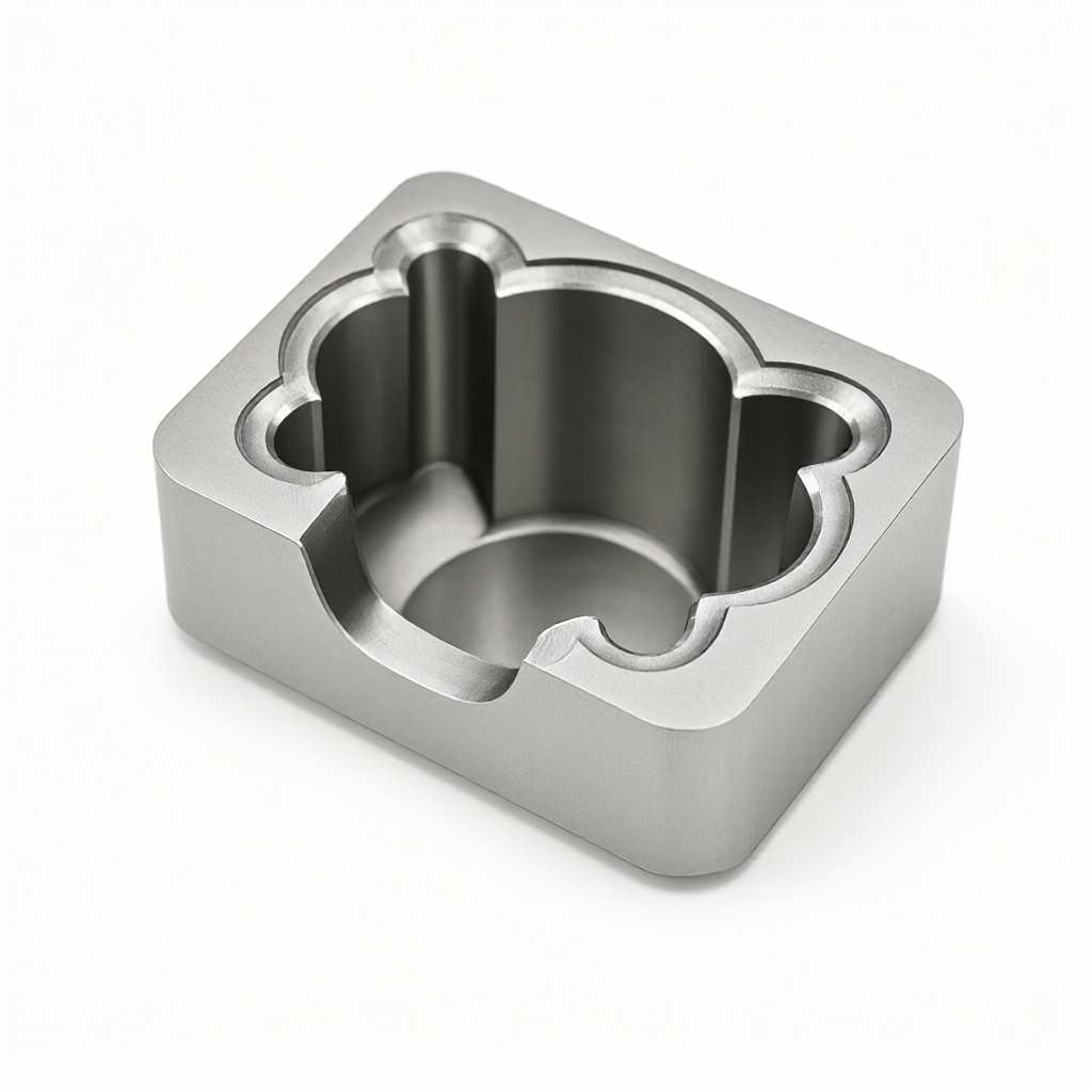
In precision CNC deep cavity milling, poor chip removal and tool wear are two key pain points that restrict size stability and surface quality. When the machining depth exceeds 50mm and the hole diameter is less than 15mm, chip accumulation is easy to cause secondary cutting and abnormal tool wear. This paper focuses onCNC milling deep cavity machiningThe practical operation difficulties of the system are analyzed, and the chip removal strategy and tool compensation logic are analyzed to provide a feasible process reference for engineers and purchasers.
Failure Mechanism and Chip Removal Strategy of Deep Cavity Machining
Deep cavity milling is a high aspect ratio machining scenario. When the tool length to diameter ratio exceeds 6:1, the spindle lateral force will cause the tool to vibrate violently, and the chips cannot be discharged smoothly in the narrow cavity, forming a "chip bed".
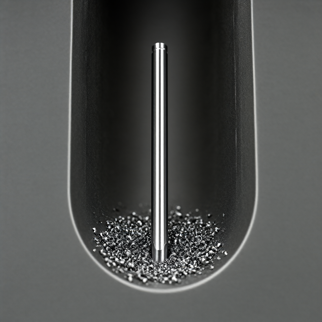
- secondary cutting effect: The chips that are not discharged are involved in the cutting area again, resulting in tool chipping, scratches on the workpiece surface, and size out of tolerance.
- cooling failureChip accumulation hinders the cutting fluid from entering the cutting zone, and local temperature rise causes thermal deformation of the workpiece, affecting the final tolerance.
In view of the above problems, it is necessary to construct an active chip removal strategy. Priority is given toHigh Pressure Micro Lubrication (MQL)orforced spray cooling, increase the pressure of the cutting fluid to 70-100 bar, rush into the contact area between the tool and the workpiece, and use the fluid flow to push the chips away from the cavity. For easy-to-adhere materials such as aluminum and titanium, oil-containing cutting fluid must be used to inhibit Chip bonding.
Tool Compensation Parameters and Feed Planning
Tool compensation is not a simple numerical correction, but a dynamic adjustment process for deep cavity scenes. In CAM software, the following parameters need to be optimized:
| parameter items | Shallow cavity machining (depth<30mm) | Deep cavity machining (depth>50mm) | technical base |
|---|---|---|---|
| speed of mainshaft | 12000-16000 rpm | Reduce to 8000-12000 rpm | Reduce rotational speed to reduce tool lateral force and suppress vibration |
| feed per revolution | 0.1-0.15 mm/rev | Raise to 0.2-0.35 mm/rev | Increase chip thickness, improve chip fluency, prevent "scraping" |
| shank clamping | standard collet | shrinkable collet | Improve tool shank rigidity and eliminate deflection caused by long tool overhang |
| cooling method | conventional spray cooling | High-pressure directional injection (>70 bar) | Forced flushing of debris in the cavity to prevent secondary cutting |
In the feed path planning, the traditional contour screw down tool should be avoided. For the deep cavity bottom, it is recommended to useSmooth Pathorfishbone stride strategy, so that the tool in heavy cutting through the empty cutting (Peck) to discharge the bottom chip. At the same time, open the CAM software "chip optimization" module, automatically increase the withdrawal action at the corner of the deep cavity, leaving room for debris discharge.
Effect of Material Properties on Chip Removal and Compensation
The cutting characteristics of different engineering materials directly determine the success or failure of chip removal strategies. Aluminum (such as 6061-T6) has good ductility and is easy to stick to the tool to form a "tumor". It must be matched with a cutting fluid containing chlorine or extreme pressure additives; titanium alloy (TC4) has poor thermal conductivity, and the temperature in the cutting zone is concentrated. It is necessary to reduce the feed rate and strengthen the cooling; stainless steel (304/316) has high strength and strong viscosity. The chips are banded and easily wound around the tool. It is necessary to select a large chip breaker tool and turn on high pressure cooling.
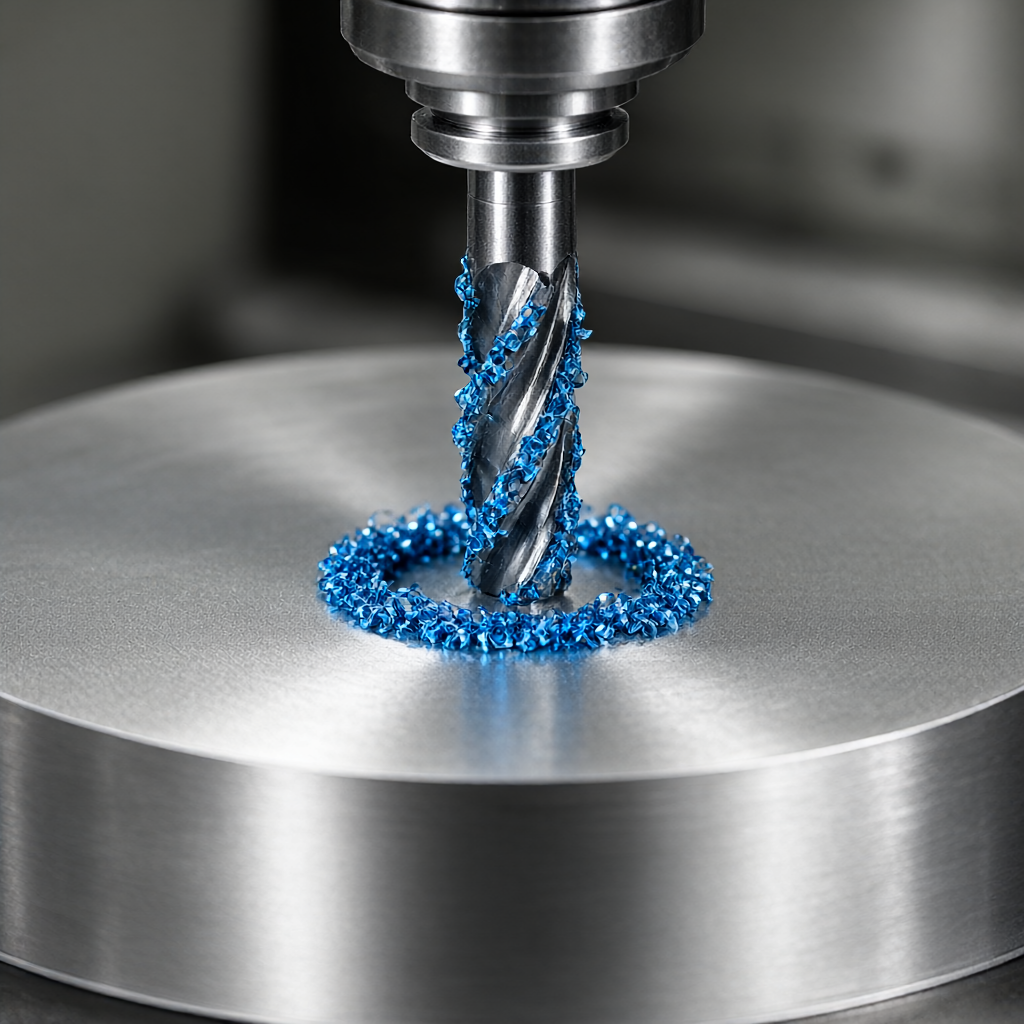
For engineering plastics (such as PEEK, PEI), it is easy to melt adhesion during cutting, and it is not advisable to use high-pressure water jet, but dry cutting or gas-liquid mixture purging should be used to prevent crazing on the plastic surface.
Deep cavity machining is preferred in tool selectionSmall Edge RadiusThe rake angle of the tool should be between 20° and 30 ° to reduce the cutting force and promote chip curling. If using cemented carbide tools, it is recommended that the edge be passivated (such as 15-20μm) to improve the tool's ability to resist chipping under intermittent cutting.
Tolerance control and acceptance criteria for deep cavity machining
The size stability of deep cavity machining depends not only on the machine tool, but also on the process closed loop. When the depth exceeds 50mm, the influence of tool rigidity on the Z direction size must be considered. It is suggested to reserve a margin of 0.05-0.1mm during programming, and to pass throughsemifinish millingStress concentration relief and reusefinish milling(Cut deep< 0.1mm)达到最终公差。
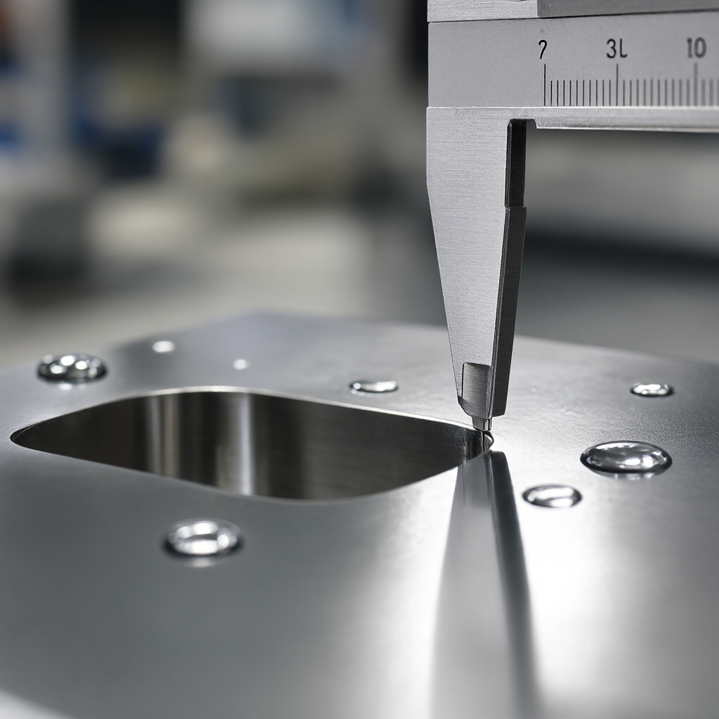
- size tolerance: Conventional aluminum alloy deep cavity can reach ±0.02mm; titanium alloy and stainless steel deep cavity is recommended to control ±0.05mm, if ±0.01mm is required, fitter repair or grinding post-treatment must be added.
- surface roughness: By optimizing the feed and speed matching, the bottom surface after finish milling can reach Ra 0.8-1.6μm; if Ra 0.4μm is required, it is necessary to add a fine grinding or chemical polishing process.
During acceptance, CMM must be used to carry out full size inspection on cavity depth, hole position and bottom flatness. For blind holes, check whether there is "bell mouth" effect or micro-crack at the bottom. Visual inspection shall focus on checking scratches on side walls to ensure surface finish meets appearance quality requirements.
Frequently Asked Questions (FAQ)
How to avoid tool chipping in CNC milling deep cavity machining?
Use large rake angle and micro-edge rounded tool to reduce spindle speed and increase feed per revolution. With shrinkable tool holder to improve rigidity, ensure smooth chip discharge and prevent impact caused by secondary cutting.
How much high pressure cooling pressure is required for deep cavity machining?
For cavities with a depth greater than 50mm, the cutting fluid pressure is recommended to be set in the range of 70-100 bar, and the spray nozzle needs to be aligned with the tool edge, and the chips can be forced out of the machining area by fluid flow.
Stainless steel deep cavity machining chip removal difficulties how to do?
Choose large chip breaker groove, large rake angle tool, reduce cutting speed appropriately. With extreme pressure additive cutting fluid and high pressure cooling, prevent band chips from winding the tool holder, ensure continuous and stable machining.
How to ensure the accuracy of ±0.01mm in the bottom of deep cavity?
Conventional CNC milling deep cavity bottom accuracy is more than ±0.02mm. If ±0.01mm is required, it is necessary to adopt semi-finish milling and finish milling two-stage process. The depth of finish milling is less than 0.05mm, and tool wear compensation is considered. If necessary, the finishing process is added.
Does deep cavity machining of engineering plastics require the use of cutting fluids?
Most engineering plastics (such as PEEK) should not use high-pressure water jet, easy to cause material swelling or crazing. Usually dry cutting, gas purge or gas-liquid mixture mode chip removal, and select large rake angle, high finish tool.
Conclusion and processing requirements docking
CNC milling deep cavity machining is the key scene to test precision manufacturing ability. Through scientific chip removal strategy, reasonable tool compensation and strict tolerance closed loop, tool wear can be effectively reduced and batch consistency can be improved. ShowyMetal has 72 CNC machines (3/4/5 axes included), support deep cavity machining of aluminum, steel, titanium, engineering plastics and other materials, tolerance up to ±0.01mm, surface finish Ra0.4μm, batch order 15-25 days fast delivery. If you are faced with deep cavity, thin wall or high finish parts processing challenges, welcome to provide drawings and technical requirements, we will provide process optimization advice and accurate quotation based on DFM experience.



