





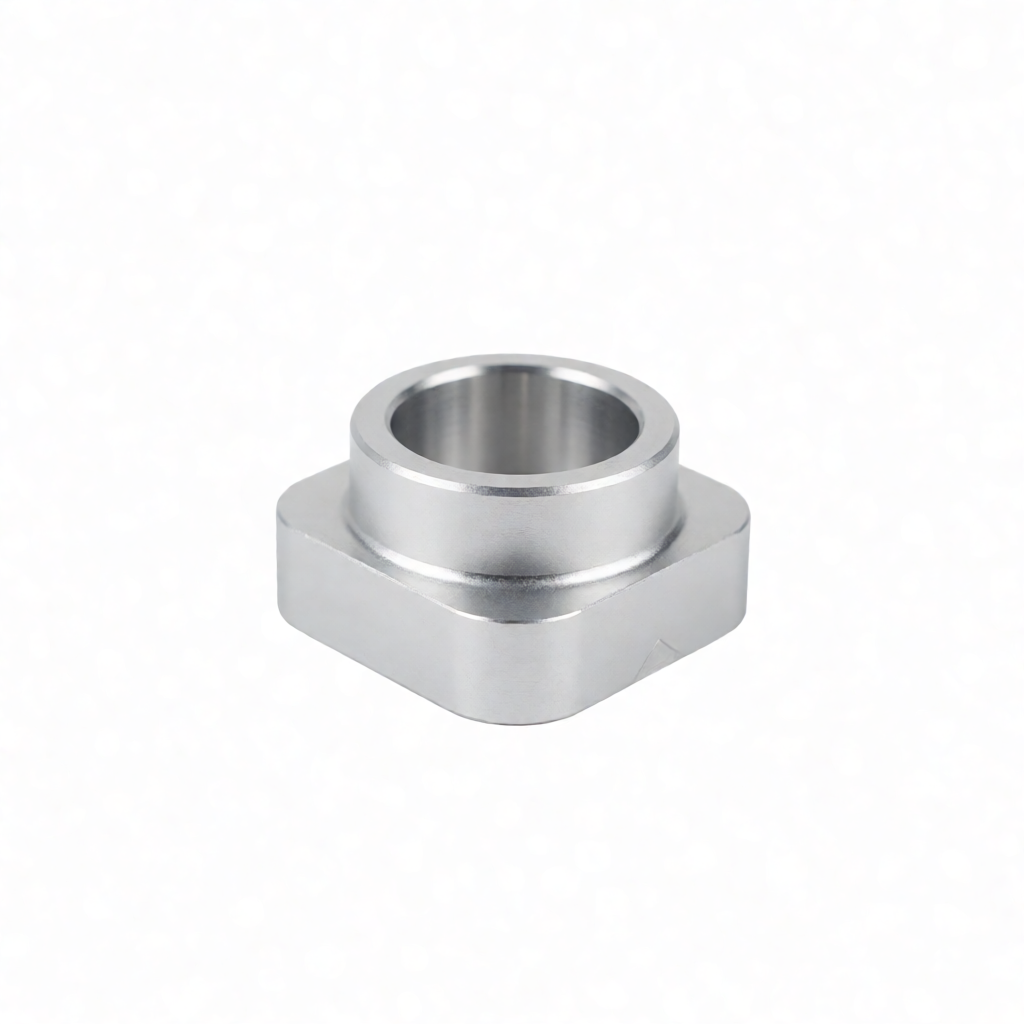
The geometric parameters of stress release slots in low-cycle fatigue design and their compatibility with CNC machining.
In mechanical structural components subjected to repeated plastic deformation, cnc parts Design Introducing low-cycle fatigue stress release slots in the stage is a key topological optimization method for extending the cycle life of components. For engineers engaged in the procurement and research and development of precision components, understanding how the geometric features of the release slot are mapped to the actual processing technology directly determines whether the design intention can be accurately restored in mass production. Many failures in the prototype trial production stage often result from minor deviations between the theoretical fillets in the design documents and the actual ball end radius of the CNC tool, or cumulative errors in the bottom depth of the groove after multiple cuts. ShowyMetal has a mature conversion process from drawings to physical objects and a processing matrix of 72 CNC machines, including 3/4/5-axis machining centers, CNC lathes, through-feed lathes and turning and milling compound machines. When dealing with stress relief slots involving complex spatial curved surfaces, we tend to bring the DFM (Design for Manufacturability) recommendations forward to assist the R&D end in avoiding dead corners that may cause interference or require secondary clamping during the 3D modeling stage. Based on practical engineering experience, the following is a detailed breakdown of how to define the dimensional tolerance, surface quality requirements, and batch consistency control strategies of low-cycle fatigue stress release grooves in CNC part design.Low-cycle fatigue failure mechanism and the physical action logic of the release slot
Coupling of stress concentration and plastic deformation
Low-cycle fatigue (LCF) typically occurs under conditions where components are subjected to high loads accompanied by significant plastic deformation. Unlike high-cycle fatigue, LCF is extremely sensitive to defects. On the cross-section where the geometric shape undergoes a sudden change, the local stress is often much greater than the nominal stress. This kind of stress strong> Stress concentration It is the primary cause of crack germination. The stress release groove significantly reduces the local maximum strain by altering the local cross-sectional geometry, spreading the stress peak from the sharp geometric transition zone to a wider area.The release slot is introduced as a design variable.
In traditional design, the transition zone usually adopts R-shaped rounded corners. However, in some specific topologies (such as thick-walled shells and shaft parts with high stress ratios), simple R-type fillets are difficult to meet the control targets of stress peaks. At this point, the designer will introduceEngineering boundaries defined by the geometry of the release slot: depth-to-width ratio, R Angle and tool accessibility
The cutting limit of Aspect Ratio (lt);
In CNC milling, the depth-to-width ratio of the release slot determines the length-to-diameter ratio (L/D) and overhang of the required tool. When the depth-to-width ratio is too large (for example, exceeding 5:1), a micro-diameter milling cutter with an extremely high length-to-diameter ratio must be used. Its insufficient rigidity leads to severe tool deflection, which can easily result in a narrower actual width at the bottom of the groove and extremely low processing efficiency. When designing, it is recommended to moderately increase the bottom width of the slot without affecting the results of the finite element analysis (FEA), and keep the depth-to-width ratio within 3:1.The spatial R Angle matches the radius of the ball-end tool.
If the bottom of the release slot is arc-shaped (R-type), the R Angle must be greater than or equal to the radius of the tool ball end. For a 5-axis machining center, R-shaped groove bottoms in any direction can be machined by tilting the Angle. However, it should be noted that if the R Angle is too small (such as R0.5mm or less), the diameter of the tool ball head is close to the slot width, and it is very likely to occur. strong> Tool interference Or the bottom surface cannot be fully formed (resulting in undercutting). During the DFM review, we will check the tool paths of the 3D model one by one to ensure that the ball-end or round-nose knives can fully cover the designed surface without leaving any residual steps.Taper transition and stress relief effect
For non-R-type conical or parabolic release grooves, the transition slope directly affects the smoothness of the stress distribution. In the design of CNC parts, it is recommended to avoid 90-degree right-angle deep grooves and instead adopt a taper transition of 30° to 60°. This design not only facilitates chip removal during cutting, but more importantly, it makes it easier to ensure consistency in mechanical processing. Right-angle grooves are prone to edge chipping during drilling or reaming, while bevel grooves can achieve more stable groove wall quality through milling finishing.Comparison of Processing Schemes and Process Selection for Release Slots of Different Structural Components
The processing paths of the release slots vary significantly for different component structures. The following table compares the selection of processing techniques for release slots in CNC part design under three typical structures and their advantages and disadvantages:| Structural features | Typical release slot morphology | Recommended CNC machining solution | Process advantages | Potential Risks and Avoidance |
|---|---|---|---|---|
| Shaft rotating bodies (such as transmission shafts, motor shafts) | Annular U-shaped or V-shaped release grooves, distributed along the circumference. | CNC turning/Turning and milling compound | Turning and milling are completed in one clamping. No clamping deformation; The smoothness of the bottom of the trough is easy to ensure. | When processing thin-walled sections, they are prone to ellipticity due to cutting forces. Soft claws should be used for support or the depth of cut compensation should be increased. |
| Thin-walled enclosures/shells (such as 5G base station heat sinks, medical instrument shells) | Deep and complex 3D curved surface release grooves | 4-axis or 5-axis linkage milling | Complex spatial curved surfaces can be completed at one time. Avoid multiple clamping and positioning errors; Grooves with a large length-to-length ratio can be processed. | Excessive overhang of the cutting tool causes Chatter. It is necessary to optimize the cutting parameters, reduce the feed rate, and select short tools. |
| Small precision parts (such as semiconductor equipment shafts, micro-robot joints) | Micron-level R-shaped arc groove | Swiss-Type Lathe + milling | Extremely high rigidity and a small heat-affected zone during cutting; Suitable for mass production; The surface roughness can reach Ra 0.2-0.4μm<. | The processing length of the tool rest after the centerless machine is limited. The machining allowance needs to be planned in advance. Micro-diameter tool life management |
Surface quality requirements and inspection standards for release slots
Roughness and subsurface Damage Control
Low-cycle fatigue has a negative impact on... strong> Surface sub-surface damage It is extremely sensitive (such as the depth of knife marks and tensile stress). The design document must clearly specify the surface roughness (Ra) requirements at the bottom of the release slot. Generally, for structural components subjected to high dynamic loads, the Ra of the functional groove surface is required to be below 0.4μm. In the design of CNC parts, the key to achieving this indicator lies in the allocation of finishing allowances. Usually, after rough milling and semi-finish milling, a finish milling allowance of 0.2mm to 0.3mm should be reserved, and a small Feed Rate (Feed Rate) and high rotational speed (SPM) should be adopted for the final tool pass. In our production process, after the precision milling, the key parts will be subjected to precision milling. strong> Surface roughness tester Full inspection is carried out without relying on the operator's experience or visual judgment.Edge chipping and microscopic crack detection
The corner of the release groove (the root of the R-shaped groove) is the contradiction point between stress concentration and processing residue. Minor chipping can rapidly evolve into fatigue crack sources here.- Microscopic detection For parts with high reliability requirements (such as aerospace and medical devices), it is recommended to add
Penetrant testing (PT) Or Magnetic particle inspection (MT) The root and transition surface of the release slot are specifically scanned to ensure there are no micro-cracks that are difficult to detect with the naked eye. - Metallographic re-examination For suspicious parts randomly inspected during mass production, samples can be taken for observation under a metallographic microscope to confirm that there is no abnormal hardened layer or residual tensile stress accumulation at the bottom of the groove caused by excessive processing.
"Tolerance" design of dimensional tolerances
The dimensional tolerance of CNC machining should be based on... strong> "Worst-Case" Evaluation. For instance, if the designed depth of the release slot is 2.0mm and the nominal dimensional tolerance is ±0.05mm, however, in the low-cycle fatigue FEA simulation, the safety factor will drop sharply when the slot depth reaches 1.95mm. At this point, risks should be avoided during the design stage by modifying the tolerance (such as changing it to -0 / +0.05mm, that is, one-way control). Procurement and engineering personnel need to clearly identify "which direction deviation is fatal" during the drawing review stage and set the corresponding <Reverse constraints of material properties on the design parameters of release slots
Matching of fatigue strength and stress amplitude
The selection of materials directly determines the size and dimension of the release slot. High fatigue strength alloy steels (such as 42CrMo4) allow for a more compact topological structure, and the release slots can be designed to be narrower. However, for common aluminum alloys (such as 6061-T6) or engineering plastics, due to their lower fatigue limits, wider and shallower release slots may be required to alleviate stress peaks. In the design of Cnc parts, for Stainless steel (such as 17-4PH or 316L) For hardened materials, the type value of the release groove often needs to be deeper than the initial design. This is because during the machining process of hardened materials, the bottom edge of the groove will develop additional micro-crack sensitivity due to residual tensile stress. In the DFM assessment, we usually recommend magnifying the R Angle of the release groove of 17-4PH to ensure that the stress relief effect during the processing is not offset by tool wear.The influence of plasticity and fracture toughness
For those with higher toughness, strong> Brass (C360) Or titanium alloy (Ti-6Al-4V), the dimensional tolerance of the release groove can be relatively loose because they can better absorb local stress concentration through plastic deformation. However, for brittle materials or high-strength hardened steel, the type value of the release groove must be strictly controlled because the material has an extremely low tolerance for root defects. The tool path strategy during CNC machining (such as unidirectional finishing rather than reciprocating feed) is particularly crucial for such materials to avoid leaving micro-grooves on the surface.CNC Machining Consistency and Tool Wear Management in Mass Production
Designing the release slots is just the first step. The real challenge lies in how to mass-produce thousands or even tens of thousands of parts with tiny grooves with consistent geometric accuracy.The influence of tool wear on slot width
In CNC milling, the width of the release slot is directly determined by the diameter of the cutting tool. Tool wear (including the VB value of rear face wear and side edge wear) will cause the groove width to gradually decrease (for ball-end tools, it is manifested as an increase in the R Angle of the bottom face). For low-cycle fatigue parts, a 5% reduction in slot width may lead to a halving of service life. The countermeasures we have taken are:- Tool Life Management Set the forced tool change cycle according to the tool wear curve.
- In Tool Radius Compensation Set the tool radius compensation parameter in the NC program. For high-precision small-radius grooves, it is recommended to use "manual radius compensation" instead of "automatic G41/G42", so that the operator can make fine adjustments on the machine tool based on the trial cutting results, avoiding systematic errors introduced by batch differences in tool size through automatic compensation.
- Process Control (SPC) In every production cycle of 20 to 30 pieces, conduct a random inspection of the width of the release slot using an image measuring instrument or a three-coordinate measuring machine, and record the data trend. Once the data exceeds the warning line of the control chart, immediately stop the line and correct the tool compensation value.



