





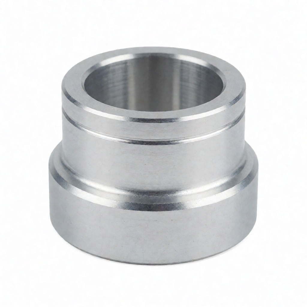
The core of the CNC part design for the cross-section of heat dissipation aluminum profiles in electronic devices lies in balancing the heat flux density, structural rigidity and manufacturability. For engineers and technical purchasers, understanding the inherent limitations of extruded profiles and the collaborative boundaries of CNC secondary processing is a prerequisite for ensuring the long-term reliable operation of radiators under harsh working conditions. Heat dissipation aluminum profiles typically use 6063-T5 or 6061-T6 alloys. The base fins are precisely extruded and then the installation interface and key features are optimized through CNC milling or turning. This higher level not only retains the efficiency advantage of the extrusion process in thin-walled structures, but also solves the problem of the flatness of the installation surface and the coaxiality of the threaded holes through the high-precision control of CNC. This article will delve deeply into the mechanical and thermal principles of cross-sectional design, elaborate on the selection strategies for CNC machining parameters, and provide a set of acceptance criteria from drawings to mass production, helping you avoid common failure modes during the design stage, shorten the sampling-making cycle, and ensure the stability of batch supply.
The selection basis of heat dissipation aluminum profiles and the CNC intervention boundary
In the early stage of design, clarifying which features are accomplished by extrusion and which by CNC is the key to controlling costs and precision. Extrusion technology excels in handling long, straight, thin-walled, and internally complex cross-sections. However, for installation bases, precise threaded holes, and the flatness of adhesion to PCB boards, extrusion dies are difficult to meet the tolerance requirements of ±0.01mm. Therefore, CNC machining usually involves the following steps:
- Installation interface finishing: Mill the extruded rough base surface to less than Ra0.4μm, eliminate the extrusion line, and ensure uniform contact with the thermal interface material (TIM).
- Functional feature processing: Mill positioning holes, countersunk holes, or turn threaded holes to avoid thread deformation and insufficient strength caused by direct tapping after extrusion.
- Alien modification: For specific installation Spaces, CNC can remove some fins or modify the shape of the base, which is a personalized demand that extrusion cannot flexibly respond to.
When choosing aluminum grades, 6061-T6 is often used for structural heat dissipation parts that require CNC deep processing due to its excellent machinability and corrosion resistance. 6063-T5, due to its outstanding extrusion performance, is mostly used for pure heat dissipation fins, and only undergoes light trimming by CNC. Both have a density of around 2.7g/cm³, but the tensile strength of 6061 can reach over 290MPa, making it more suitable for scenarios where electromagnetic force or mechanical shock is required.
Analysis of the Influence of Section Geometric Parameters on Thermal Efficiency
The heat dissipation performance depends on the combined effect of the fin area, spacing and thickness, rather than a single dimension. Overly dense fins can impede natural convection and cause a sharp increase in wind resistance. Although overly thin fins have a large heat dissipation area, they are prone to deformation and damage during processing. The following rules of thumb should be followed when designing:
- Fin thickness: The recommended range is 0.8mm to 1.5mm. Fins smaller than 0.8mm are prone to chipping or burrs during CNC milling, and their extrusion stability decreases. If it is higher than 1.5mm, it weakens the significance of increasing the surface area and increases the axial thermal resistance.
- Fin spacing: When natural convection is used for heat dissipation, the spacing usually needs to be more than 10mm to 15mm to ensure that cold air can fully enter. If combined with forced air cooling (fan), it can be compressed to 6mm to 8mm. When calculating, it is necessary to combine the fan curve to avoid being in the low efficiency zone of the fan.
- Fillet radius: It is recommended to retain the fillets from R2 to R3 within the cross-section. The stress concentration coefficient at sharp corners is high. During CNC machining, if the tool radius is smaller than the fillet radius, it will cause interference. Moreover, sharp corners are prone to catching cables during assembly. Meanwhile, rounded corners help ensure smooth air flow and reduce local vortex losses.
CNC Machining Parameters and Tool Path Optimization Strategies
For CNC machining of aluminum materials, parameter Settings directly affect surface finish and dimensional stability. Aluminum materials have low hardness and high toughness. If the cutting parameters are not appropriate, it is very easy to form "built-up edge" or stick to the tool, resulting in deterioration of surface roughness.
- Spindle speed: It is recommended to operate at 8,000 RPM to 12,000 RPM. High-speed cutting can make the chips thin and curled, reducing the resistance to chip removal. For the processing of complex curved surface heat dissipation parts with 4-axis or 5-axis linkage, it is necessary to avoid the axial cantilever of the tool being too long to control the vibration marks.
- Feed rate: The feed per revolution (fz) is set between 0.1mm and 0.2mm. When using three-edge or four-edge end mills with a diameter of 6mm, the feed per axis is usually between 300mm/min and 600mm/min. Excessive feed will cause tool deflection and reduce flatness.
- Cooling method: It is recommended to use trace lubrication (MQL) or a large amount of water-soluble cutting fluid. Aluminum chips conduct heat quickly. If they are not cooled enough, the temperature at the tool tip will rise, which will accelerate tool wear. Meanwhile, aluminum chips are prone to clogging the tool grooves, so blades with chip removal grooves or solid carbide tools should be selected.
For high-precision installation surfaces, it is recommended to adopt the "layered milling" strategy. For rough machining, a 0.2mm allowance should be reserved. For finish machining, the tool path width should be controlled at 20% to 30% of the tool diameter, and the step distance should be within 1mm. This can stably control the surface roughness at Ra0. Within 4μm, high-quality appearance requirements can be achieved without additional grinding processes.
Comparison of Different Section Design Schemes and Applicable Scenarios
In actual projects, based on power consumption and space constraints, the three common cross-sectional design schemes each have their own advantages and disadvantages. The following table compares the differences in CNC machining difficulty and thermal performance among standard straight fins, gradually changing height fins, and cross-sections with air duct structures:
| Scheme type | CNC machining difficulty | Heat dissipation efficiency characteristics | Applicable scenarios | Typical tolerance requirements |
|---|---|---|---|---|
| Standard straight fins | Low | Simple structure, low wind resistance, suitable for high-power continuous heat dissipation. | Server, high-power power supply, LED lighting | Flatness ≤0.05mm, perpendicularity ≤0.1°. |
| Gradient height fins | "Chinese" | Adjust the height according to the pressure distribution of the air path to enhance the utilization efficiency of the boundary layer. | High-density electronic modules in confined Spaces, automotive ECU | Height tolerance: ±0.02mm, section parallelism: ≤0.03mm. |
| With internal air ducts/microchannels | "High | Significantly increasing the heat exchange area requires precise processing of the internal structure, which incurs high costs. | Micro laser, chip-level water-cooled coupling heat dissipation | The uniformity of wall thickness is ±0.01mm, and the position accuracy of the hole diameter is ≤0.05mm. |
For most consumer electronics and industrial control applications, standard straight fins with CNC-machined mounting surfaces can meet the requirements. When facing scenarios with extremely limited space and concentrated power consumption, the gradient height fins need to simulate the airflow distribution during the design stage. During CNC machining, special attention should be paid to the support rigidity of side milling to prevent the thin-walled parts from vibrating the tool and causing dimensional deviations. For cross-sections with microchannels, it is necessary to assess whether the CNC tool can enter the processing. Generally, when the hole diameter is less than 4mm, it is recommended to combine electrical discharge or laser perforation auxiliary processes. CNC drilling alone is costly and prone to tool breakage.
The actual impact of Surface treatment and Protection on heat dissipation performance
The surface treatment of aluminum profiles after processing is not only related to appearance, but also directly affects the heat dissipation efficiency and corrosion resistance. Although the oxide film on the exposed surface of aluminum materials has a certain protective effect, it oxidizes faster in a humid or salt spray environment, and the white oxide film will reduce the heat absorption efficiency.
- Anodizing: The recommended film thickness is 8μm to 12μm. After sealing treatment, it has excellent corrosion resistance and is available in both black and transparent colors. It should be noted that the oxide film is a poor conductor of heat. A too thick film layer (20μm) will slightly reduce the heat dissipation efficiency. For high-performance heat dissipation components, it is recommended to control the thickness at a medium level.
- Spray/powder coating: If a black matte coating is adopted, it has a high heat absorption coefficient, which is conducive to radiation heat dissipation. However, the adhesion of the coating must pass the hundred-grid test to prevent cracking and peeling during high-temperature cold and hot cycles, which could clog the gaps between the fins.
- Sandblasting treatment: It is often used for pretreatment before the installation surface to remove residual oil stains and oxide scale from CNC, and enhance the adhesion of subsequent anodizing or spraying. The recommended grit size for sandblasting is 80 to 120 mesh to prevent overly coarse sand particles from damaging the precision flatness.
For decorative heat dissipation shells with high-gloss surface requirements, a mirror-like effect can be achieved by direct polishing or electrolytic polishing after CNC precision milling, and the Ra value can be as low as 0.1μm. But this will increase costs and it is necessary to weigh whether it is necessary. Generally, for functional heat dissipation components, it is sufficient to achieve consistency without scratches or flaws. Excessive pursuit of mirror-like effects in internal structures without visual requirements is a waste.
Design verification, testing standards and acceptance specifications
Before mass production, strict design verification and dimensional inspection must be carried out to ensure that the radiator is free from interference and meets the thermal resistance standards during actual assembly. The acceptance basis should include the following core testing items:
- Size inspection: Use a three-coordinate measuring machine (CMM) to detect key features. The key monitoring points include the flatness of the installation base surface (recommended ≤0.03mm), the thickness direction dimension (±0.05mm), and the verticality of the fins. For threaded holes, a thread gauge go/stop gauge should be used to check the center diameter to ensure a smooth match with the screw.
- Thermal performance test: According to the JESD51 standard, the thermal resistance of the package is measured using the transient thermal resistance test method (such as RedL-1000). Set a constant power injection, record the junction temperature and shell temperature, and calculate the total thermal resistance. It is recommended that the first piece be fully inspected for batch sampling inspection ratio, and subsequent sampling inspections be conducted in accordance with AQL 1.0/2.5.
- Appearance and rust prevention test: Visual inspection shows no cracks or obvious knife marks. The salt spray test must last for more than 96 hours without red rust (for anodized parts). The cross-sectional test of the coating should reach above grade 5B to ensure qualified adhesion.
Establish SPC (Statistical Process Control) cards to monitor the Cpk values of key dimensions when Cpk



