





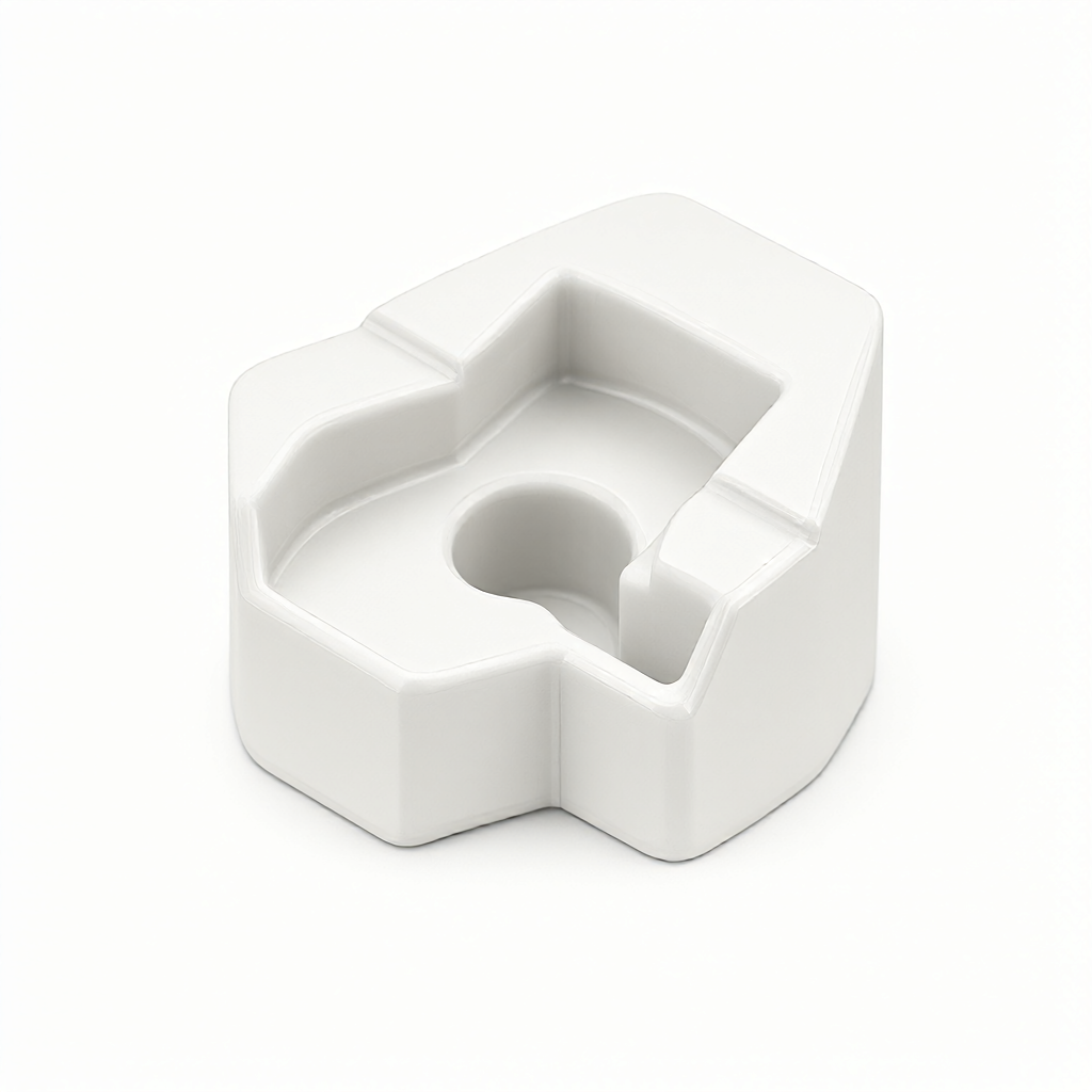
In the design of stainless steel CNC parts, the tool path directly determines the surface finish and processing efficiency. Many engineers overlook the impact of path strategies on Ra values, residual heights and material tearing, resulting in significant appearance differences between batches and high rework rates. Based on the mass production experience of 72 CNC machines, this article analyzes the impact of different tool paths (row spacing, step rate, Z-direction layering) in 3/4/5-axis milling on the surface of 304/316 stainless steel, and provides practical parameter suggestions and inspection methods to help the purchasing and R&D teams identify the process window at the drawing stage. Ensure that the batch parts meet the high surface finish requirements of Ra0.8 - Ra1.6μm.
The core influence mechanism of tool path strategy on the surface quality of stainless steel
Stainless steel (such as SUS304, SUS316L) has a low thermal conductivity (about 16 W/m·K). During cutting, heat is concentrated at the tool tip, which can easily lead to surface hardening, plastic deformation and "string-like" residual streaks of the workpiece. The tool path directly affects the microscopic roughness parameters (Ra, Rz) and macroscopic appearance consistency by controlling the depth of cut, step distance, feed direction and overlap rate.
- Side Milling It is applicable to planes and side walls, and the path can be a parallel straight line or a spiral. If the step distance (Stepover) is too large, obvious stripes will be left. If it is too small, it will increase the machine time and the knife is prone to vibration.
- Facing at the bottom It is used for top surface finishing and usually adopts circular or rectangular paths. Due to the change in the feed direction of the main shaft, "fan-shaped" or "cross" textures are prone to occur, which need to be eliminated through smoothing the path or fine grinding with a swing tool.
- Finishing milling (Finishing) The operation is carried out using small-diameter end mills or ball-end cutters with extremely small cutting depths (ap=0.05-0.1mm) and high rotational speeds (n=8000-12000 rpm, depending on the tool), aiming to eliminate the marks left by previous rough machining.
If the surface finish requirements of key surfaces (such as Ra≤0.8μm) are not marked during the design stage, the processing plant will default to the rough processing standard (Ra1.6-3.2μm), which may result in the appearance not meeting the standards. Therefore, the design drawings must clearly indicate the surface roughness symbols and tolerance zones of key parts so that the factory can select the corresponding tool path strategy.
Quantitative Influence Analysis of Key Process Parameters on Surface Finish
In CNC programming, surface finish is mainly determined by three variables: feed rate (F), spindle speed (n), number of tool edges (z), and step distance (Stepover). For stainless steel, it is recommended to prioritize increasing the rotational speed and reducing the feed rate to decrease the cutting thickness per edge (hc), thereby suppressing material tearing.
| Processing type | Typical parameter Settings | Expected Ra value (μm) | Applicable scenarios and Notes |
|---|---|---|---|
| Rough milling | ap=2–5mm, ae=50%–70% | Ra 3.2-6.3 | Remove most of the excess and do not use it on the appearance surface. |
| Semi-finishing milling (Semi-Finishing) | ap=0.5-1mm, ae=30% - 50%. | Ra 1.6 | Eliminate the allowance for rough machining and prepare for fine machining. |
| Finish milling (Finishing) - flat tool | ap=0.05-0.1mm, high-speed smooth path | Ra 0.4-0.8 <;" | The key processes of the exterior surface need to be fully lubricated with coolant. |
| Mirror Polishing | Specialized polishing discs/honing, non-standard CNC paths | Ra ≤ 0.1 (mirror surface) | Post-surface treatment, non-milling direct to obtain |
Note: The CNC milling accuracy provided by ShowyMetal can reach ±0.01mm, and the conventional surface finish capability covers Ra0.4μm. If the design requires a higher degree of smoothness, it is necessary to indicate "precision milling" or "post-polishing" on the drawing and reserve the corresponding process time.
Matching principles for stainless steel materials and tool selection
Stainless steel has strong toughness and severe work hardening, while ordinary hard alloy tools are prone to chipping. During the design stage, the purchasing and engineering departments need to confirm whether the factory has a tool library optimized for stainless steel.
Tool material and coating
- Coated cemented carbide It is recommended to use AlTiN (titanium aluminum nitride) coated cutting tools, which are heat-resistant and wear-resistant, and are suitable for continuous cutting of SUS304/316.
- Edge passivation For stainless steel, the cutting edge of the tool should undergo passivation treatment (Chamfer + Relief) to prevent excessive cutting from causing vibration and scratches.
The coordination of tool path and tool diameter.
When finishing the surface, the tool diameter should not be too small (usually ≥3mm) to avoid Chatter caused by excessive overhang of the tool. Chatter will leave high-frequency ripples on the surface, damaging the smoothness. If the feature size is extremely small (such as a high blind hole depth), Swarfing or secondary clamping solutions should be adopted, and the feasibility should be confirmed with the factory before the quotation.
Practical key points for Avoiding surface Defects in the Design Phase (DFM)
The smoothness issues of many bulk orders stem from design flaws. The following three points are the key points of DFM review:
- Chamfering and deburring All sharp edges must be marked with a Chamfer, such as C0.5 or R0.5. CNC tools cannot process 90-degree right angles. Forced chamfering can prevent the accumulation of burrs during processing and avoid affecting the surface appearance. For those not marked, the factory may retain sharp edges or manually deburr them, increasing batch variations.
- Coaxiality of the hole system Stainless steel drilling is prone to deviation. It is recommended to mark the positioning reference (Datum A/B/C) on the drawing. By adopting the "drilling + reaming" process instead of direct boring, the hole wall surface finish with Ra≤1.6μm can be ensured. For high-precision mating holes, it is recommended that the tolerance be controlled within H7.
- Avoid narrow slots and thin walls. Narrow grooves less than 1mm in stainless steel are prone to tool jamming, causing surface burns. When designing, the slot spacing should be widened as much as possible or the tool diameter should be reduced. If necessary, the wire cutting (EDM) process should be adopted, but the cost and delivery time need to be evaluated (the delivery time of EDM is usually longer than that of CNC).
ShowyMetal offers free DFM advice before taking an order. By simulating the tool path, it can detect interference and surface finish risks in advance, reducing the number of mold trials.
Inspection standards and batch consistency control
Surface finish is not only an indicator for individual pieces but also an indicator of batch consistency. ShowyMetal adopts the following inspection process to ensure delivery quality:
- Roughness meter measurement Use an optical/stylus roughness meter to measure the Ra values at three random points and take the average. The record should be accompanied by a measurement direction and location map.
- Visual and gloss inspection Check under the standard light source box for any knife marks, vibration marks or oxidation color spots. For appearance parts, the gloss meter data (GU value) can be provided as supplementary acceptance basis.
- First item confirmation Before mass production, the first piece must pass the "Limit Sample" signed by the customer. For subsequent batches, take this as the benchmark to ensure that the Ra value fluctuates within ±0.2μm.
Before shipment, 100% full-size inspection and full appearance inspection are carried out. Equipped with three-coordinate measuring machines (CMM) and optical measuring instruments, both geometric dimensions and surface quality meet the standards. The report is provided with the goods and includes Cpk analysis (if requested by the customer).
Frequently Asked Questions (FAQ)
What is the surface finish that stainless steel CNC parts can achieve?
Conventional 3/5-axis milling can achieve Ra0.4μm (semi-mirror effect). If a higher degree of smoothness is required, additional manual polishing or electrochemical polishing processes should be added. The specific parameters need to be evaluated separately based on the shape of the part.
What impact does tool path design have on delivery time?
Complex smooth paths (such as spirals and swing heads) will increase programming time and machine time, usually extending by 10% to 20% compared to straight paths. However, in mass production, the single-piece cycle time can be shortened by optimizing the tool path. The 15-25 day batch delivery time of ShowyMetal already includes the process optimization time.
How to ensure that the surface color of batch parts is consistent?
The color mainly depends on the material grade (the color difference between 304 and 316 is slight) and subsequent surface treatment (such as the thickness of the passivation film). CNC milling itself has no color difference. If anodizing (aluminum) or electroplating (copper/zinc) is required, the voltage and time need to be controlled. ShowyMetal has a complete surface treatment line and can control the stability of color batches.
If the roughness is not indicated on the design drawing, what standard does the factory follow by default?
If not specified, Ra3.2-6.3μm (rough machining standard) is usually executed by default. If there are aesthetic requirements, it is essential to mark Ra1.6 or Ra0.8 on the key surfaces of the drawing and indicate the words "Precision milling". Otherwise, the factory will follow the economic processing plan.
Can only the Ra value be specified without specifying the process?
Sure. The Ra value is a result indicator. Factories will independently select the most economical process combination (such as milling + polishing) based on the material and part structure. However, it is recommended to simultaneously indicate visual requirements such as "no longitudinal tool marks" to avoid acceptance disputes.
Conclusions and Cooperation Suggestions
The tool path serves as a bridge connecting the design intent with the physical entity. For stainless steel CNC parts, through reasonable DFM design, matching high-performance tools and strict batch inspection, a high surface finish of Ra0.4μm can be stably achieved. ShowyMetal, relying on 72 CNC machines and one-stop surface treatment capabilities, provides high-precision and high-appearance quality batch solutions for industries such as aerospace, semiconductors, and medical care.
Call to action: If you have drawings of stainless steel parts, you are welcome to send them to the technical team to obtain the DFM analysis report and processing plan suggestions. We will respond within 24 hours.



