





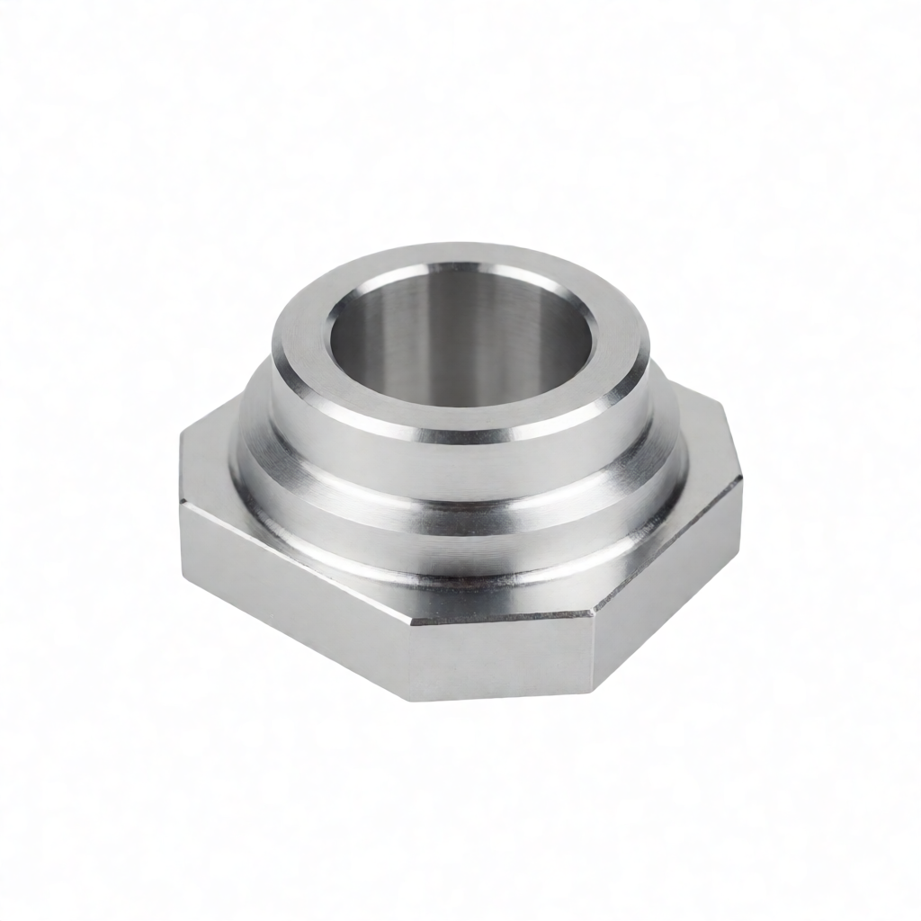
In precision CNC machining, tool selection and chip evacuation strategy for deep-cavity parts directly determine part integrity, surface quality, and batch stability. For milling scenarios with a high depth-to-width ratio (L/D ≥ 10), the core challenges lie in vibration caused by insufficient tool rigidity, secondary cutting due to chip accumulation, and reduced tool life caused by poor heat dissipation. Starting from the principles of cutting mechanics and drawing on ShowyMetal’s hands-on experience on 3/4/5-axis machining centers, this article systematically explains the logic of tool selection, optimization of cutting parameters, and design of chip evacuation paths in deep-cavity machining. It aims to provide engineers with a practical technical guide to address common failure modes in the machining of deep-cavity parts.
Three Core Challenges in Deep-Cavity Machining
Deep-cavity parts generally refer to cavity structures where the depth is significantly greater than the width, commonly found in molds, battery housings, and aerospace structural components. Unlike traditional shallow cavities, deep-cavity machining faces three unavoidable physical limitations. First, the tool's length-to-diameter ratio (L/D ratio) increases significantly, causing deflection of the tool holder under cutting forces. When the L/D exceeds 5, the bending stiffness of conventional solid carbide end mills drops rapidly, making chattering highly likely. Second, the chip evacuation path becomes extremely narrow and long. Chips cannot fly out freely once generated and tend to accumulate at the bottom of the cavity, leading to "secondary cutting." This not only damages the already-machined surface but can also cause chipping or breakage of the tool. Third, thermal conductivity is low. The enclosed space inside the deep cavity makes it difficult for chips and cutting fluid to remove cutting heat; localized temperature increases accelerate tool wear, especially coating spalling.
The Link Between Vibration and Surface Quality
Vibration is the primary factor affecting surface roughness in deep-cavity machining. When a tool experiences periodic chatter, distinct ripples appear on the part surface. Under high-finish requirements such as Ra 0.4 μm, even slight vibrations can lead to out-of-tolerance results. Therefore, suppressing vibration is not only a requirement to protect the tool but also a prerequisite for ensuring dimensional accuracy. Engineers should estimate resonant frequencies through modal analysis during process planning to avoid dangerous spindle speed ranges, or reduce the feed rate to decrease excitation forces.
Tool Selection Strategy: Rigidity, Coating, and Geometry
Deep-cavity machining imposes special requirements on tool material selection and geometry. Standard solid carbide end mills are often inadequate for deep-cavity applications; more targeted tool types are required.
- Matching tool holder and tool length: Prioritize tools with a length-to-diameter ratio L/D ≤ 6. For even deeper cavities, adopt stepped machining with layer-by-layer plunging to avoid excessive single-step depth of cut.
- Coating technology: Deep cavities have poor heat dissipation, resulting in extremely high tool temperatures. AlTiN (aluminum titanium nitride) or AlCrN (aluminum chromium nitride) coatings, due to their high hardness and high-temperature stability, are more suitable for machining aluminum or steel parts in deep cavities than traditional TiN coatings. AlTiN coatings maintain a low coefficient of friction above 600°C, effectively reducing tool sticking.
- Helix angle design: High helix angles (45°-50°) provide better chip evacuation direction, guiding chips smoothly out of the slot and reducing the probability of chip adhesion to the tool body. However, they have slightly lower torsional strength compared to low-helix-angle tools, so a trade-off must be made based on material hardness.
Tool Recommendations for Different Materials
| Material Type | Recommended Tool Material | Recommended Coating | Key Geometric Features | Application Notes |
|---|---|---|---|---|
| Aluminum Alloy (6061/7075) | Tungsten Steel (Carbide) | No coating / DLC | 3 flutes, helix angle 30°-45° | Aluminum tends to stick to the tool; uncoated or Diamond-Like Carbon (DLC) coatings enhance self-cleaning properties and prevent chip residue. |
| Stainless Steel (304/316) | Tungsten Steel (High-Performance Grade) | AlTiN / AlCrN | 4+ flutes, large helix angle | Stainless steel is tough and has poor thermal conductivity; high thermal stability coatings are required, and large helix angles help with chip breaking. |
| Titanium Alloy (Ti-6Al-4V) | Tungsten Steel (Ultrafine Grain) | AlTiN / No Coating (Specific Formulation) | 2-3 flutes, small rake angle | Titanium alloy has a narrow machining window; requires low speed and high depth of cut. Small rake angles strengthen the edge to prevent chipping. |
For chamfering and root clearing in deep pockets, it is recommended to use ball-nose end mills or 30°/45° bull-nose end mills. The bull-nose end mill (End Mill with corner radius) has a shorter contact length at the corners, effectively reducing cutting forces and alleviating tool deflection, making it a critical tool for root clearing in deep pockets. However, its surface finish is typically not as good as that of flat-end mills; if extremely high appearance requirements are specified, subsequent finishing milling or polishing treatment is required.
Cutting Parameter Optimization: The “Slow” Philosophy of Deep Pocket Machining
Many junior engineers mistakenly believe that increasing spindle speed can resolve low efficiency in deep pockets; this is precisely the wrong approach. The core logic of deep pocket machining is to “trade speed for rigidity and control heat via feed rate.”
Control of Spindle Speed and Engagement Depth
At the bottom of a deep pocket, tool overhang is at its maximum and rigidity is at its weakest. Cutting depth (aep) must be significantly reduced at this stage. For a tool with an L/D ratio of 6, it is recommended to retain only 20%-30% of the tool diameter as the effective cutting depth at the bottom. Simultaneously, spindle speed (S) should not blindly pursue high values; instead, it should be maintained within 1.2-1.5 times the critical speed (n_cr) to avoid the resonance zone. For example, if the tool’s natural frequency is 2000 Hz, the critical speed is approximately 120,000 rpm; thus, the spindle speed should be controlled between 140,000 - 180,000 rpm (depending on machine capability) or reduced to below the resonance zone.
Feed Rate and Cooling Strategy
Feed rate (f) must be coordinated with cutting width (aew). Under high L/D ratios, a “high-speed, light-cut” strategy with high spindle speed and low cutting depth is recommended. For aluminum alloys, the chip load per tooth (ap) can be controlled to 0.05-0.15 mm/tooth, ensuring heat dissipation while reducing cutting forces. Regarding cooling, high-pressure internal coolant (Internal Coolant) is more effective than external flood coolant. Injecting coolant at 40-70 bar through the tool’s center hole directly into the cutting zone significantly lowers local temperature and assists chip evacuation. For dry or minimum quantity lubrication (MQL) machining, it is essential to ensure chips are rapidly evacuated; otherwise, dwell times for air blowing are necessary.
Chip Evacuation Path Design and Chip Management
Ineffective chip evacuation is the primary cause of failure in deep pocket machining. Chips winding and accumulating within the cavity can lead to tool jamming or surface scratches. Effective chip evacuation design requires integrating CAM software path planning with the machine’s physical characteristics.
Z-Axis Layering and Spiral Entry
Avoid feeding directly perpendicular to the workpiece surface. It is recommended to use spiral ramp entry (Spiral Ramp Entry) or angled entry so that chips are naturally flung out of the cavity following the tool’s rotation direction. In CAM programming, set the “spiral ramp depth” to 30%-50% of the tool diameter per revolution to ensure chip length is moderate, facilitating curling and evacuation. For parts with high requirements for bottom flatness, the final 1-2 mm of depth can be switched to planar milling (Planar Milling) using small-diameter tools for finishing, avoiding long tool overhang.
Chip Form Control
Chip form is controlled through the tool’s chip breaker (Chip Breaker) design. For deep pockets, the goal is to generate short, curled chips rather than long ribbon chips, as ribbon chips easily wind around the tool tip at the cavity bottom. For aluminum alloys, uncoated tools with appropriate negative rake angles promote chip curling; for steel parts, tools with large helix angles combined with high feed rates facilitate natural chip breaking. If chips remain too long, consider adding coatings or adjusting tool geometry angles, rather than simply reducing the feed rate.
ShowyMetal Deep Pocket Component Machining: Practical Case Analysis
Taking an aerospace-grade aluminum alloy deep pocket structural part as an example, the part has a deep pocket ratio of L/D approximately 8, material 7075-T6, requires surface roughness Ra ≤ 0.8 μm, and no chatter marks. The ShowyMetal team determined the following solution during the process review stage:
- Tool Selection: Rough milling uses a 4-flute carbide end mill with L/D=4, AlTiN coating; finishing milling uses a 3-flute bull-nose end mill with L/D=6, specifically for corner root clearing.
- Parameter Setup: Rough milling: spindle speed 8000 rpm, feed rate 1500 mm/min, cutting depth 5 mm; Finishing milling: spindle speed 12000 rpm, feed rate 1200 mm/min, cutting depth 2 mm. High-pressure internal cooling at 50 bar is enabled throughout the process.
- Chip Evacuation Verification: Chip accumulation is simulated to adjust the spiral entry angle, ensuring chips are smoothly evacuated along the spiral trajectory. First-article inspection was qualified, with no tool glazing or surface scratches observed.
This case demonstrates that deep pocket machining is not about blindly pursuing “fast,” but rather “stable.” Through reasonable control of tool L/D ratio and fine-tuning of parameters, high precision and quality appearance can be achieved even under complex geometries. ShowyMetal possesses 72 CNC machines, including 5-axis machining centers, capable of flexibly handling such complex deep pocket structures, providing rapid delivery capabilities of 15-25 days from prototyping to batch production.
Common Failure Modes and Preventive Acceptance Criteria
Despite the strategies above, specific failures may still occur in deep pocket machining. Engineers must establish corresponding preventive mechanisms and acceptance criteria.
Tool Chipping and Breakage
Chipping is often caused by excessive cutting forces at the bottom or interference. Preventive measures include: carefully checking CAM paths for overcuts; reserving a 0.5-1 mm clearance allowance at the deep pocket bottom to avoid rigid collisions Use a CNC control system equipped with anti-collision detection. During acceptance, verify edge integrity via 100% full-size inspection and use an optical measuring instrument to check chamfers for chipping.
Surface Chatter and Scratches
Chatter originates from regenerative vibration, while scratches result from chips repeatedly snagging the surface. Prevention involves avoiding resonant spindle speeds and optimizing coolant/lubrication. Acceptance criteria refer to ISO 21926; use a roughness tester to take samples at the center of the deep pocket and the four quadrants of the bottom, ensuring Ra values are consistent and meet specifications. For appearance-critical parts, perform visual inspection or bluing to ensure no microscopic scratches exist. ShowyMetal's differentiating advantage lies in batch consistency control, ensuring uniform surface quality and zero defects across all batches through strict In-Process Quality Control (IPQC).
Deep Pocket Dimensional Out-of-Tolerance
Thermal deformation is the primary cause. Prevention requires compensating for thermal elongation in CAM programming or measuring parts only after they have cooled to room temperature. During acceptance, use a Coordinate Measuring Machine (CMM) for full-dimensional inspection, focusing on the flatness and position of the deep pocket bottom. If dimensional drift occurs during mass production, trace the tool wear curve and establish tool replacement criteria based on wear volume (Vb) rather than purely time-based intervals.
FAQ
When the aspect ratio exceeds 10:1, should short tools with step-down machining or long tools with single-pass machining be prioritized?
We recommend the "short tool, step-down" strategy. Long tools with an L/D ratio> 10 have extremely poor rigidity and are highly susceptible to chatter. By performing step-down passes, gradually deepening the cut with shorter tools at each step, rigidity is maintained, ensuring surface quality and precision. Only when structural constraints prevent step-down machining should high-performance long tools be considered, requiring significantly reduced cutting parameters.
For aluminum deep pocket machining with chip welding, what solutions are available besides using uncoated tools?
Adjust cutting parameters: increase spindle speed, reduce feed rate, and decrease chip width to produce thinner chips that are easier to evacuate. Simultaneously, optimize cooling methods by using high-pressure internal coolant to directly flush the chip evacuation area. If ineffective, check the sharpness of the tool edge; dulled edges exacerbate chip welding.
How to determine if chatter has occurred during deep pocket machining?
The most direct method is to observe the workpiece surface for periodic waves and measure the wave spacing. Compare the frequency corresponding to the wave spacing with the machine spindle speed; if the frequency is an integer multiple or a fraction of the spindle speed, it is highly likely chatter. Additionally, monitor the machining sound, as chatter is typically accompanied by a sharp screech. It is recommended to perform regular modal tests to establish the Frequency Response Function (FRF) of the machine-tool-workpiece system.
How does ShowyMetal ensure appearance consistency in mass production of deep pocket parts?
We establish strict tool life management records, combined with in-line length measurement to monitor tool wear in real-time. Simultaneously, we implement First Article Inspection (FAI) and In-Process Quality Control (IPQC) regimes to ensure the surface finish and dimensions of every operation remain within tolerance bands. ShowyMetal specializes in high-gloss, scratch-free surface finishing processes; through post-processing such as anodizing and sandblasting, we further enhance surface quality to ensure batch appearance consistency.
What are the specific requirements for selecting cutting fluid in stainless steel deep pocket machining?
Stainless steel has low thermal conductivity and generates high cutting temperatures, requiring high extreme-pressure (EP) cutting fluids to enhance lubrication and cooling effects. Additionally, the fluid must have excellent rust-inhibiting properties to prevent corrosion on machined surfaces and inside deep pockets. We recommend using EP additive formulations containing boron or molybdenum, and regularly monitoring the concentration and microbial content of the cutting fluid to prevent surface defects caused by contamination.
Conclusion
CNC machining of deep pocket parts is a system engineering challenge involving a comprehensive balance of tool selection, parameter optimization, chip management, and machine rigidity control. By adhering to the principles of "high rigidity, appropriate cooling, and collision avoidance," combined with scientific CAM path planning, failure risks can be significantly reduced, improving machining efficiency and quality. ShowyMetal, leveraging its deep accumulation in the precision CNC field, provides one-stop solutions ranging from process evaluation to batch delivery for various deep pocket structural components. If you have technical challenges or custom requirements for deep pocket parts, please send your drawings to our engineering team for communication. We will provide targeted DFM suggestions and rapid quotations.



