





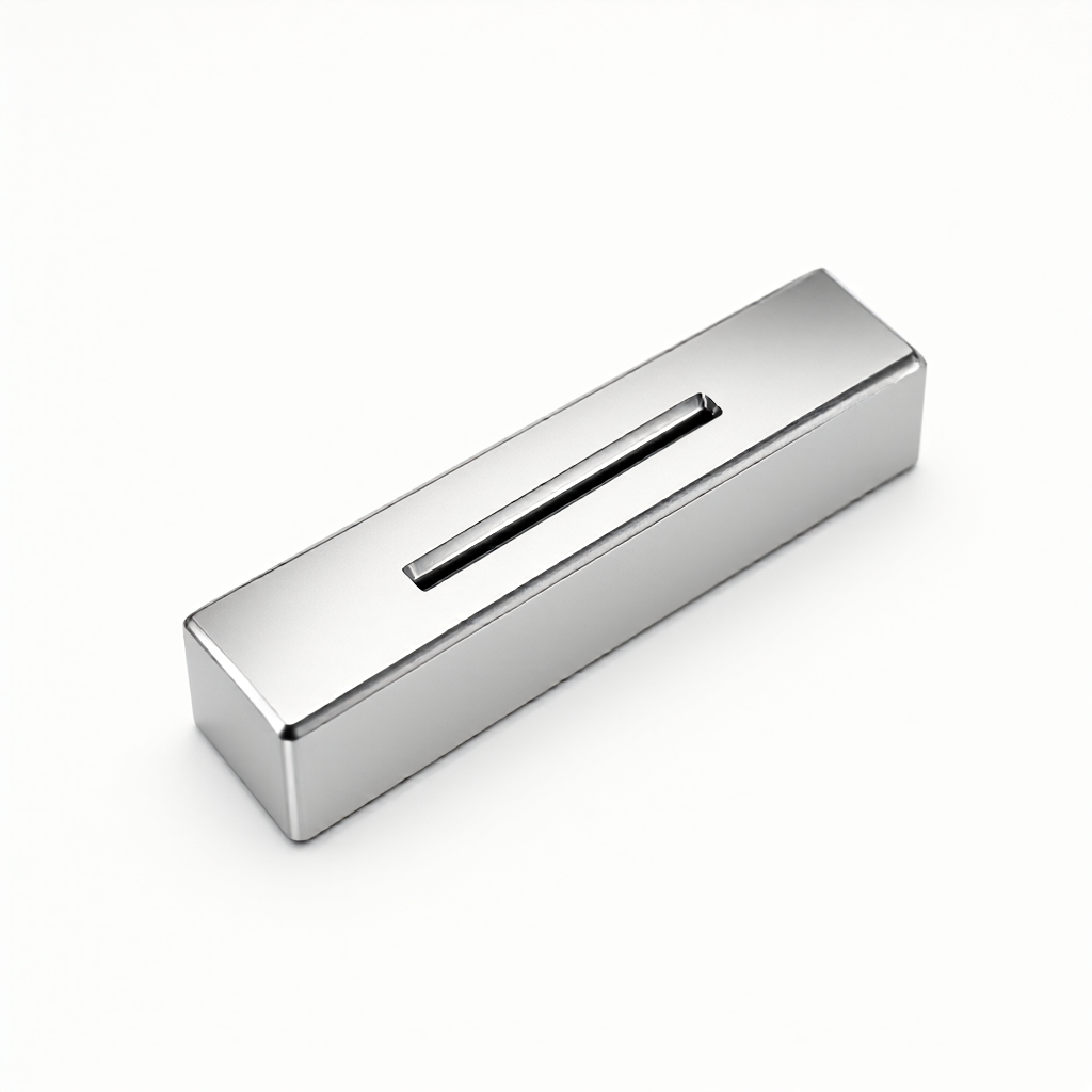
In precision CNC parts manufacturing,Narrow groove machiningThe success or failure of the machine often does not depend on the rigidity of the machine tool, but onMatching Relationship between Tool Radius and Slot Width. Many engineers only found in the first part of the trial cutting, according to the theoretical size tool selection, the actual cutting force surge, tool holder vibration intensified, and even lead to groove bottom fillet or sidewall scratches. This is not only a process problem, but also directly affect the consistency and appearance quality of mass production. This paper will combine ShowyMetal's actual combat data in 3/4/5 axis milling, deeply analyze tool radius coefficient, interference envelope and compensation logic, help technical procurement and R & D personnel establish scientific selection basis, and avoid failure mode from the source.
Analysis of Process Bottleneck and Failure Mode in Narrow Groove Machining
When the groove width is less than 1.2 times the tool diameter, the conventional end mill enters the "narrow groove zone". At this time, only the cutting edge part of the tool is involved in cutting, and the part of the tool body that is not involved in cutting is easily interfered with the workpiece or fixture. Common failure modes include:
- Side gouging: When the tool is withdrawn or advanced, the handle or shoulder collides with the groove wall, causing irreparable scratches.
- Let the knife and the back bend: When the aspect ratio is too large, the tool rigidity is insufficient, resulting in an oversize size of the groove width, usually a positive deviation (groove widening).
- ChatterNarrow groove cutting area is small, damping is low, easy to excite the main mode vibration, surface roughness is rapidly deteriorated.
The core of solving these problems lies in re-examining the coupling relationship between tool geometry and machining path, which can not be solved by simply changing a knife, but needs comprehensive consideration based on finite element mechanics and cutting mechanics.
Tool radius coefficient: core parameter determining feasibility
definitiontool radius coefficient $\alpha$is the ratio of the groove width $W$to the tool radius $R_c$($ \alpha = W / 2R_c $). This coefficient directly determines the freedom of motion of the tool in the groove.
Process characteristics of different coefficient intervals
According to our measured data on 72 CNC machines, different $\alpha$values correspond to very different machining states:
- $\alpha < 1.0$: The bottom of the tool interferes with the bottom of the groove, physically unable to process, must reduce the tool radius or increase the groove width.
- $1.0 \le \alpha < 1.5$: Safety zone. The tool is completely in the groove, the side wall has no interference risk, suitable for conventional end mills.
- $1.5 \le \alpha < 2.0$: Transition zone. Although there is no geometric interference, the tool overhang is large and the rigidity is reduced. It is necessary to reduce the feed speed and optimize the holder grip.
- $\alpha > 2.0$: Wide groove area. At this time is no longer a "narrow groove" problem, but a multi-tool path splicing problem, pay attention to the knife pattern.
Meaning to buyers: When sending the drawing inquiry, if the narrow groove ratio $\alpha$is between $1.0-1.5$, it is recommended to ask the supplier whether it has a "narrow groove special tool library", which is a key indicator to test its engineering docking ability. Ordinary factories may default to using large diameter tools for forced cutting, resulting in a significant drop in yield.
Ball versus bull nose: depth comparison of two narrow groove schemes
End mills are often inadequate when narrow grooves require high bottom flatness or sidewall finish. Ball End and Bull Nose / Radius End are the main candidates. There are significant differences in cost, efficiency and surface quality.
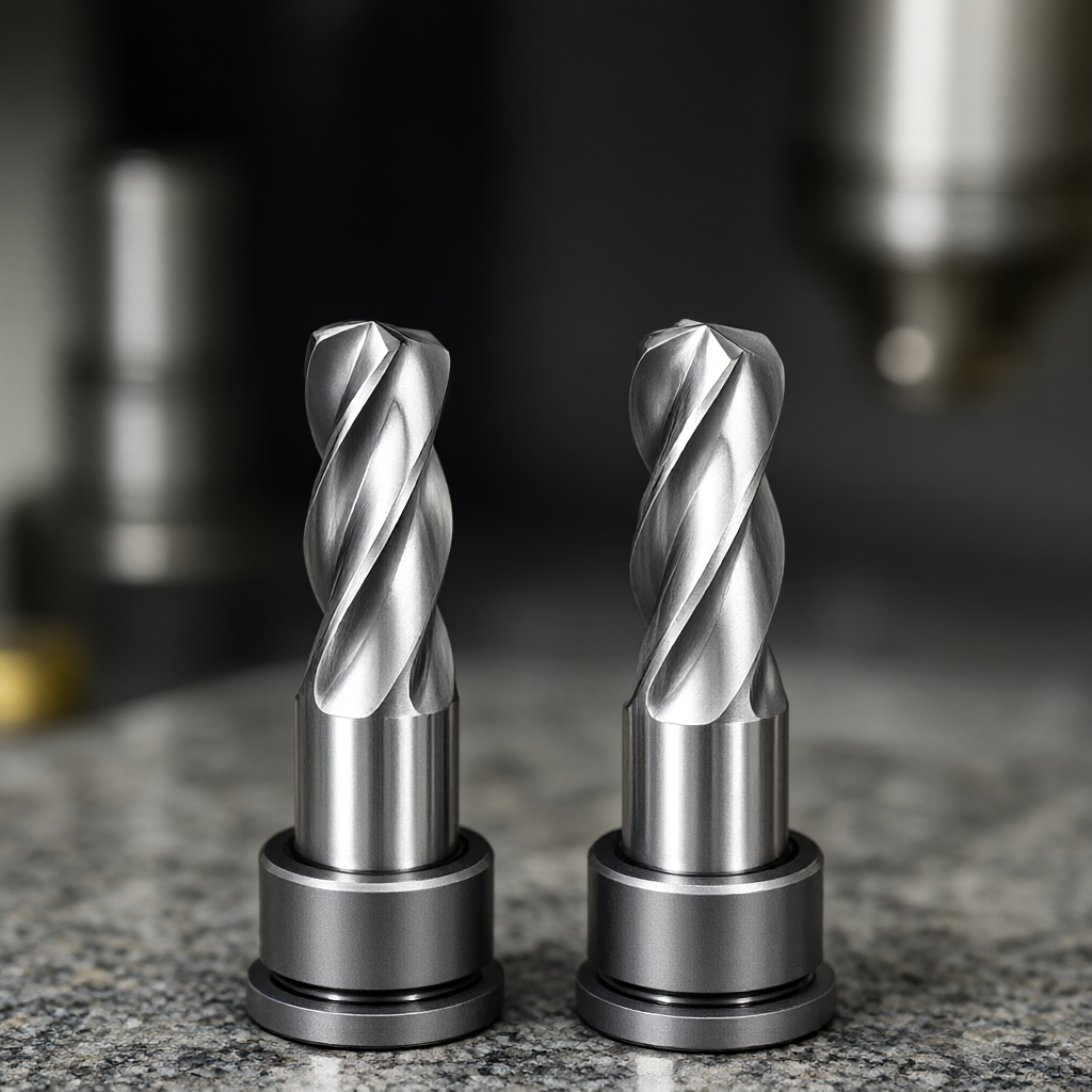
| Assessment Dimensions | Ball End Mills | Bull Nose Cutter |
|---|---|---|
| bottom forming ability | Perfect arc, no secondary finishing, suitable for organic surfaces or R groove bottom | Contact edge only, bottom center residual theoretical height, need to pass twice or accept plane | sidewall finish | Poor. Cutting line changes with radius, easy to produce fan grain, Ra value is usually>0.8μm | Excellent. The side surface is cylindrical contact, the texture is uniform, and Ra0.4μm or higher can be achieved. |
| tool life | Short. Low linear speed at small diameter, poor heat dissipation, fast wear | Long. Large radius cutting, good heat dissipation, strong rigidity, suitable for long-term cutting |
| applicable scenarios | Mold cavities, complex 3D profiles, parts with requirements for bottom R values | Products with high sidewall finish requirements, flat grooves, appearance parts, and high batch consistency requirements |
| cost control | High. Tool unit price is high and needs frequent replacement. | Low to medium. High tool durability, low overall cost |
engineering advice: If your part isapparent visualand the side wall of the groove needs to present the effect of "high bright surface and no scratch".ox nose knifeShowyMetal is a more cost-effective choice. In mass production, R0.5-R1.0mm bull nose cutters are recommended for this type of demand. With high-speed turning and milling machine tools, it ensures the consistency of batch appearance.
Compensating Logic and Programming Practice Points
Choosing the right tool is only the first step. Correct compensation settings can avoid size overruns. Here are three key practical nodes:
1. Direction Selection of Radius Compensation
When processing the left side wall, it must be enabledLeft Offset; Enable when machining the right side wallRight Offset. Many novices confuse left and right in narrow groove machining, resulting in too much cutting and chipping. It is recommended to open simulation in CAM software to check whether the tool envelope exceeds the theoretical value of groove width.
2. Cutting strategy to avoid "stabbing"
In the depth of the narrow groove, vertical cutting can easily lead to tool bending. It is recommended to useRamp InorArc InStrategy. Take 3 mm diameter bull nose tool machining 5 mm wide, 10 mm deep groove as an example: in the depth of 0 - 5 mm using 15 ° oblique angle, 5 - 10 mm to maintain vertical feed, cutting force peak can be reduced by more than 30%, significantly reduce back bend.
3. Surplus and finishing separation
0.2 - 0.3mm allowance for roughing, finer step for finishing (Stepper< 15% 刀径)。精修阶段务必使用climb cutting, using the hard side of the tool to push the workpiece, improve surface finish and reduce tool wear.
Acceptance Criteria and Test Means
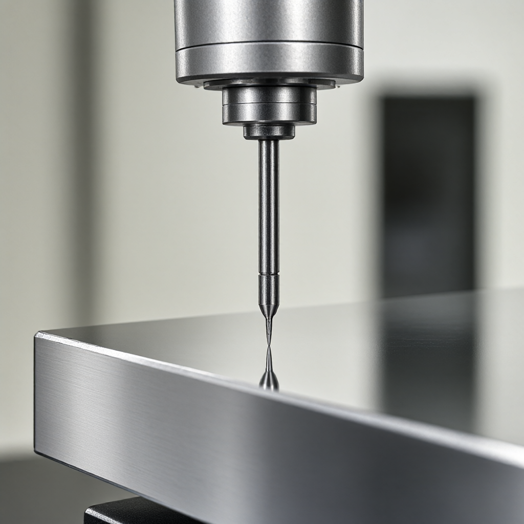
The quality of the narrow slots is difficult to determine visually and must rely on sophisticated inspection equipment. We perform the following inspection procedures before shipment:
- size detection{1}: Use {2}vision measuring machineCheck the groove width. The key points include the center of the groove bottom and 1/3 of the two side walls. The standard tolerance is usually ± 0.01mm. For higher accuracy requirements, it can be performed according to the drawing.
- Depth and flatness{1}:{2} UseCoordinate Measuring Machine (CMM)Collect the grid points at the bottom of the groove, and evaluate whether the flatness exceeds 0.05mm. The deep groove is prone to warp, so it needs to be inspected.
- surface roughness{1}: Use {2}roughness testerMeasure the side wall Ra value. For appearance parts, Ra ≤ 0.4 μ m is required; for functional parts, Ra ≤ 0.8 μ m usually meets the requirement.
- interference checking: In the first article phase, usefeeler gaugeorProbe SimulationCheck for potential risk of collision of the tool with surrounding features, especially in the presence of chamfer or fillet transition areas.
Transparent delivery: ShowyMetal provides a complete inspection report for each batch, including CMM coordinate data, roughness measurements and appearance photos. This is not only a proof of quality, but also a data base to help customers establish process stability.

Frequently Asked Questions (FAQ)
How small a tool is needed to machine a narrow groove of 0.5mm width?
The theoretical minimum tool radius should be less than 0.25mm, but considering rigidity, it is recommended to use a precision micro end mill with a diameter of 0.5mm or 0.6mm. If the groove depth exceeds 3mm, it is strongly recommended to use a bull nose cutter and reduce the speed to avoid the risk of chatter and tool breakage.
Why do I always have spiral patterns on the side walls of my narrow grooves? What should I do?
Spiral lines are mainly caused by excessive step pitch or tool wear. Check the CAM parameters for "fine step pitch (Stepper)", it is recommended to set it to 10%-15% of the tool diameter. At the same time, confirm whether the tool side edge has a crack, and enable chamfer compensation (Lead-in/Lead-out) if necessary.
What are the specific requirements for machine tool rigidity in narrow groove machining?
Narrow slot to machine toolspindle runoutSensitive, requiring spindle radial runout ≤ 0.005mm. At the same time, the machine tool should have high speed and high rigidity characteristics, it is recommended to use hard clamping turning tools or ER clamps to avoid loosening caused by spring clamps. ShowyMetal's 5-axis machine tools all adopt high precision ER tie rod system to ensure stable clamping of micro-diameter tools.
How to ensure the consistency of narrow groove size in batch production?
the critical point lies in the fact thatAutomatic monitoring of tool compensation. Use a probe with length and circle function to automatically compensate for wear values after each tool change. At the same time, fix the cutting path sequence to avoid error drift caused by heat accumulation. For orders with high consistency requirements, we increase the frequency of first article and inspection, and monitor the trend graph of CMM key size.
What is the difference between narrow groove processing technology of plastic parts and metal parts?
Engineering plastics (such as PEEK, PEI) easy to stick when cutting, need to useLarge rake angle, sharp edgeSpecial tools for metal parts (such as 6061 aluminum) pay more attention to chip removal and heat dissipation, and it is recommended to use tools with more spiral chip grooves. There is no essential difference between the two in compensation logic, but the cutting parameters (speed/feed) differ greatly, so it is necessary to establish process cards separately.
Conclusion and invitation for cooperation
Narrow groove machining may seem simple, but it is a comprehensive test of tool library management, CAM programming ability and machine rigidity control. Whether it is sealing grooves for aerospace structural parts or decorative grooves for high appearance requirements in consumer electronics, accurate tool radius matching is the cornerstone of reducing scrap and improving on-time delivery.
If you're having visual consistency issues with narrow groove machining, or need process validation for specific materials and depths, send your 2D/3D drawings to ShowyMetal Engineering. We'll provide you with tool selection, tool path strategy, and tolerance recommendations based on field data from 72 machines.DFM Analysis ReportTo help you get it right once in the mass production phase and deliver it efficiently.



