





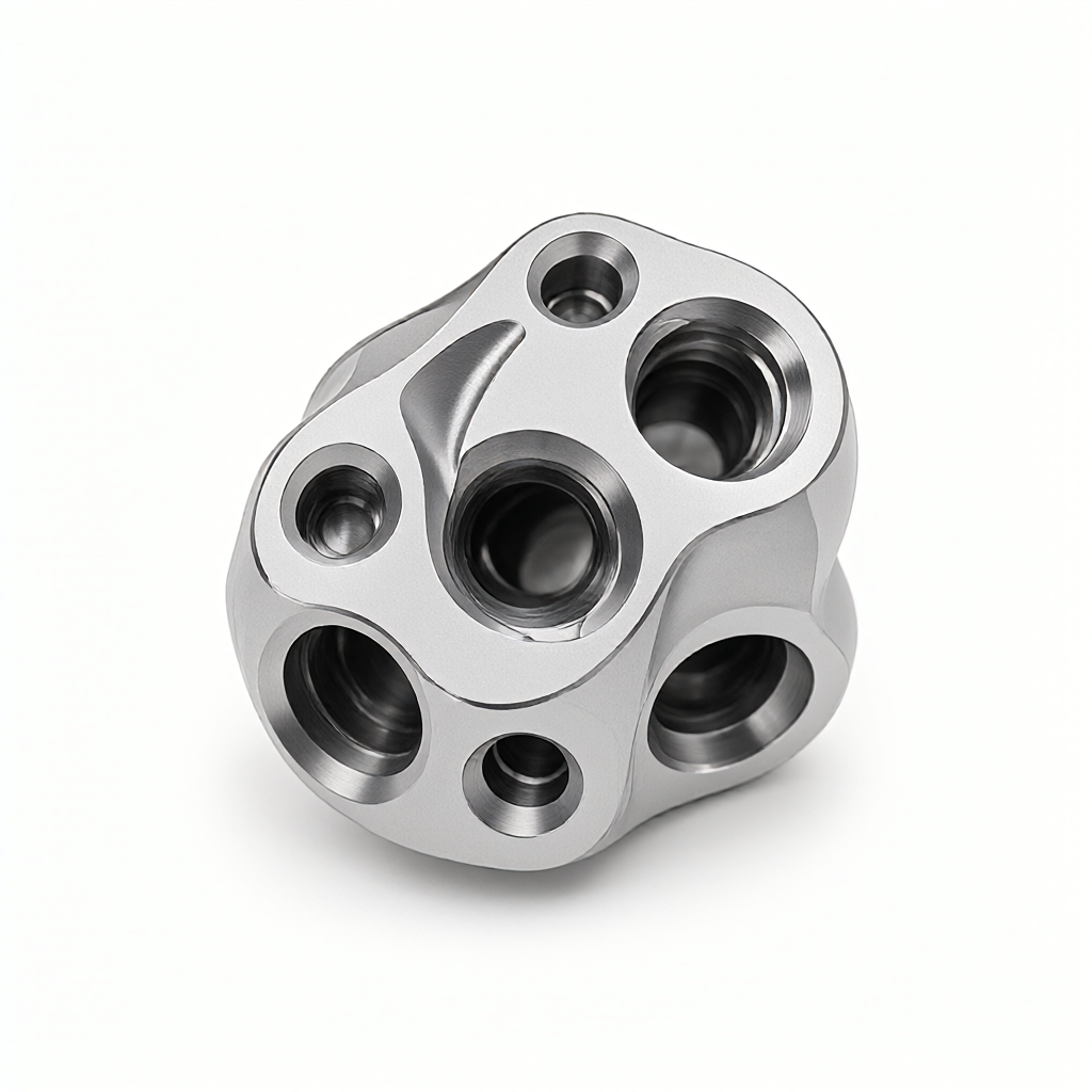
5-axis CNC machining precision valve core inner hole depth-diameter ratio and tool slenderness ratio challenge
In pneumatic, hydraulic and semiconductor systems,Precision valve coreIt is the core component of controlling fluid on-off and flow regulation. Its processing difficulties are concentrated inFive-axis CNC machiningThe treatment of deep cavity and irregular inclined hole, especiallyRatio of inner hole depth to diameter (L/D)withtool slenderness ratioThe problems of insufficient rigidity, cutting vibration and chip removal are brought about. For purchasing and R & D engineers, understanding the relationship between these two parameterstolerance stabilitywithsurface finishIf we only rely on the drawing commission and ignore the tool path compensation strategy in the process path, it will often lead to batch consistency failure or delivery delay.
Physical limitation of inner hole depth-diameter ratio on valve core precision
Valve cores usually require a hole depth to diameter ratio (L/D) of 3:1 or even 5:1. When L/D exceeds 3,Five-axis CNC machiningThe drilling and reaming processes in the face significant challenges:
- Tool swing and tool yield:The elastic deformation of the tool under compression increases exponentially with increasing slenderness ratio. At L/D=4, the diametrical size deviation may exceed the tolerance window of ±0.01 mm if conventional rigid supports are used.
- Heat accumulation and thermal deformation:In deep hole machining, cutting heat is difficult to conduct through shank, which leads to local temperature increase, and then causes residual stress and shrinkage deformation of workpiece after cooling.
- Risk of debris blockage:Especially in the processing of stainless steel or titanium alloy materials, chip curling easy to accumulate at the bottom of the hole, resulting in tool chipping or even knife.
Therefore, at the DFM (Design for Manufacturability) stage, engineers need to define the upper L/D limit. For example, for a valve core hole of Φ 6 mm, if the depth exceeds 24 mm (L/D=4), it is recommended to machine in stages or to use boring instead of single drilling to control the cumulative error.
Matching Strategy of Tool Slendedness Ratio and Cutting Parameters
Tool slenderness ratio (S/L) directly affects milling and drillingsurface roughnesswithsize stability. YesFive-axis CNC machiningIn, the ball nose knife or round nose knife is commonly used for surface and orifice chamfering, and its S/L is usually 5:1 to 8:1.
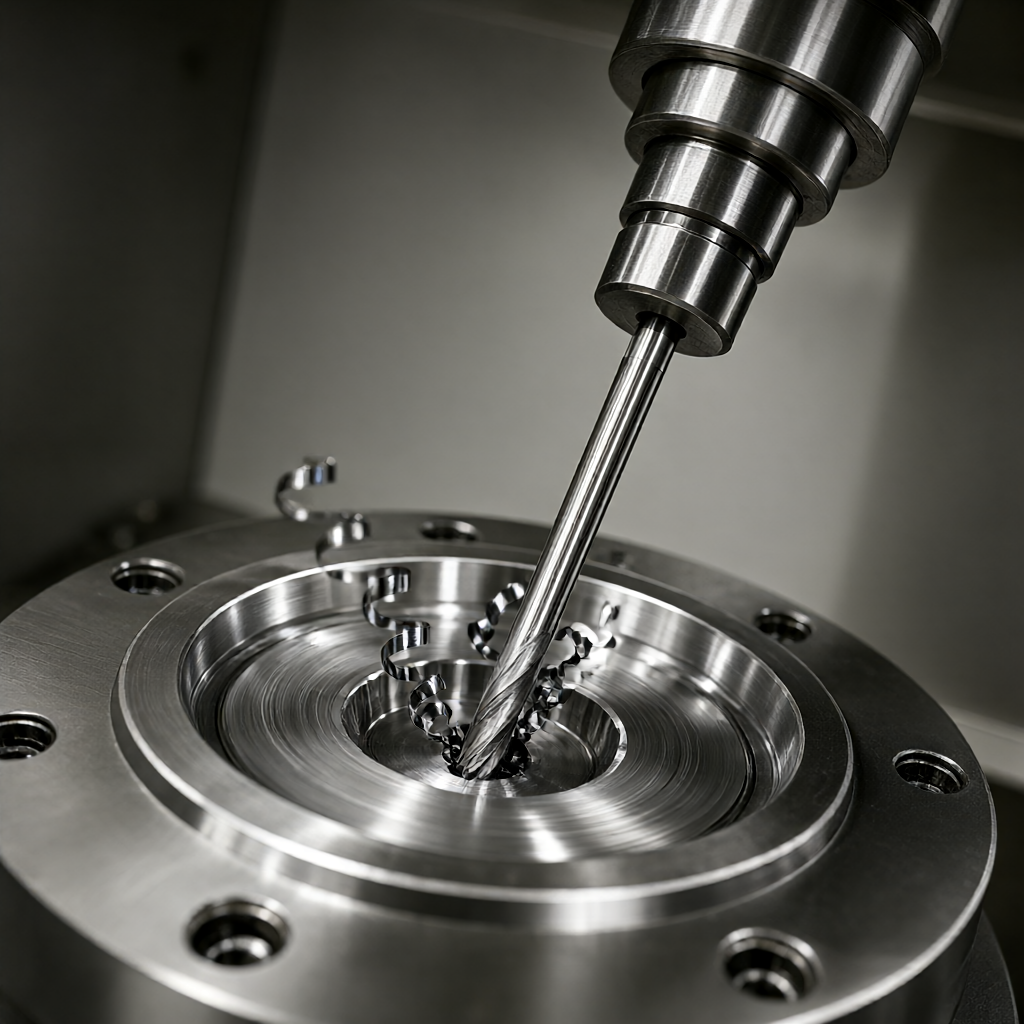
- Speed and feed optimization:High S/L tools must reduce the cutting speed (Vc) and feed rate (Fz) to suppress chatter. For example, when machining aluminum alloy 6061, Vc is recommended to be controlled at 60 - 80 m/min instead of the conventional 200 m/min.
- Tool coating and geometry:PCD (polycrystalline diamond) or CBN (cubic boron nitride) coated tools can improve the rigid life, but it needs to match the spindle thermal error compensation strategy.
- Spindle taper selection:HSK or BT50 high rigidity taper spindle is preferred for deep hole machining to reduce the influence of interface thermal drift on hole position accuracy.
Five-axis linkage path planning and tool axis control
Valve cores often contain inclined holes, blind holes and multi-faceted positioning features,Five-axis CNC machiningThe advantage of the tool is that it can maintain the best working angle through linkage rotation and avoid the bottom hanging cutting. The key lies in the Tilt & Lead strategy:
- Floor Normal:The tool is always perpendicular to the machining surface, suitable for flat and straight wall surfaces, but the orifice is prone to cutting marks.
- Side Normal:Tool tilt of 5°-10° improves hole roundness and surface finish, but requires stricter tool S/L.
- Dynamic Tilt:According to the curvature of the tool position automatically adjust the inclination, suitable for complex surface spool, CAM software with G5 axis continuous interpolation ability.
For deep holes with L/D > 3, it is recommended to set it in the five-axis program.layer-downwithdrill peckingAction, every 2 - 3 mm under the cut is raised 1 mm, to prevent chips from winding. At the same time, the constant temperature chip fluid (pressure 40 - 60 bar) directly washes the hole bottom, reducing the risk of thermal deformation.
Effect of Material Selection and Surface Treatment on Deep Hole Stability
Commonly used valve core materials include SUS316L stainless steel, Inconel 718 and bearing steel GCr15.heat conductivity coefficientwithstrengthdirect influenceFive-axis CNC machiningTool wear and workpiece deformation in:
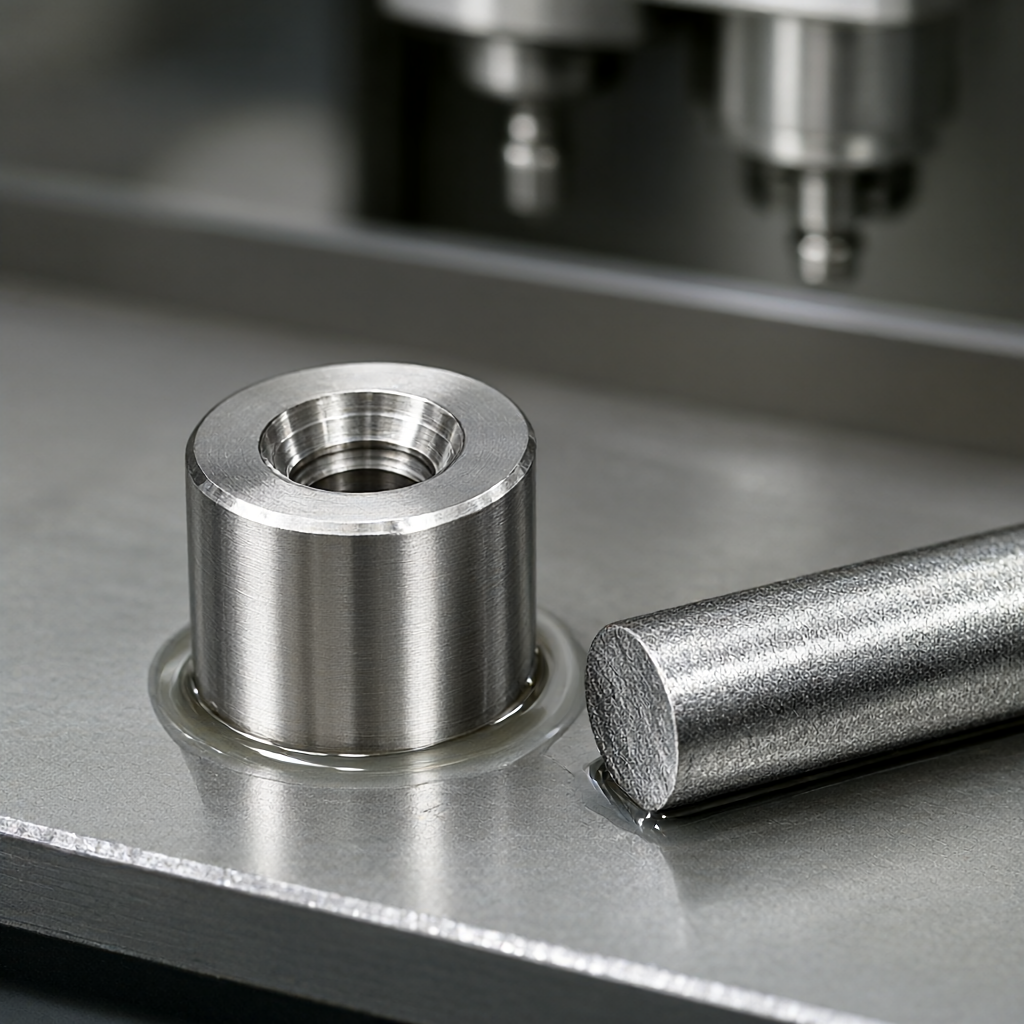
| material trademark | Typical L/D limit | main difficulty | Recommended post-processing |
|---|---|---|---|
| SUS316L | 3.5–4.0 | High toughness, easy to stick knife | Sandblasting + passivation |
| Inconel 718 | 2.5–3.0 | High hardness, low thermal conductivity | Vacuum heat treatment + electrolytic polishing |
| GCr15 | 3.0–3.5 | Heat treatment deformation | Grinding + grinding |
Special attention: stainless steel valve core after deep hole processing, residual stress easily lead to hole shape drift. Suggest to increase after rough millingaging stress reliefProcess (480℃/2h), followed by finish machining and final inspection. Surface treatment, anodization is suitable for aluminum valve core, but not for stainless steel; if high finish is required, electrolytic polishing can reduce Ra to less than 0.2 μm, but it will shrink 0.02 - 0.05 mm size, so it is necessary to reserve compensation amount in CAM program.
Test methods and acceptance criteria
Accuracy verification of deep hole and inclined hole can't rely on CMM point detection only, but must be combined with CMM point detection.pneumatic measuring instrumentwithoptical comparison:
- Hole depth and position:L/D ratio and coaxiality are measured in real time by using Rayter or KEYNES pneumatic probe, with tolerance of ±0.005 mm.
- Surface RoughnessUse SJ-2100 series roughness tester, sampling length 1.25 mm, sealing surface Ra of valve core ≤0.4 μm, non-sealing surface ≤0.8 μm.
- Form and position tolerance:Roundness and cylindricity of inclined holes are scanned by laser profilometer to generate point cloud, which is compared with CAD model, deviation<0.01 mm 判定合格。
100% full size inspection shall be carried out before shipment, and CMM report and roughness chart shall be attached. For batch order, it is suggested that after the first piece is confirmed by customer, the key hole position shall be sampled once every 50 pieces, and SPC control chart shall be established to monitor tool wear trend.
FAQs and process avoidance suggestions
Q1: How to ensure consistency in batch production of deep holes with L/D=4 valve core?
adoptFive-axis CNC machiningThe layered drilling and reaming strategy in, chip removal once every 2 mm, and with coaxial fixture constraints. Change the bit every 200 pieces in batch, to avoid tool tip wear leading to gradual hole expansion.
Q2: How to deal with chatter of slender tool S/L=8 during high speed milling?
Reduce the spindle speed to the stable lobe area (query through the tool dynamics database), or use a short-edge tool in two steps. If a long tool must be used, increase the intermediate support or reduce the cutting thickness (ap) to 0.5 mm or less.
Q3: Burrs and stress concentration appear in the orifice of stainless steel valve core after processing. How to remove them?
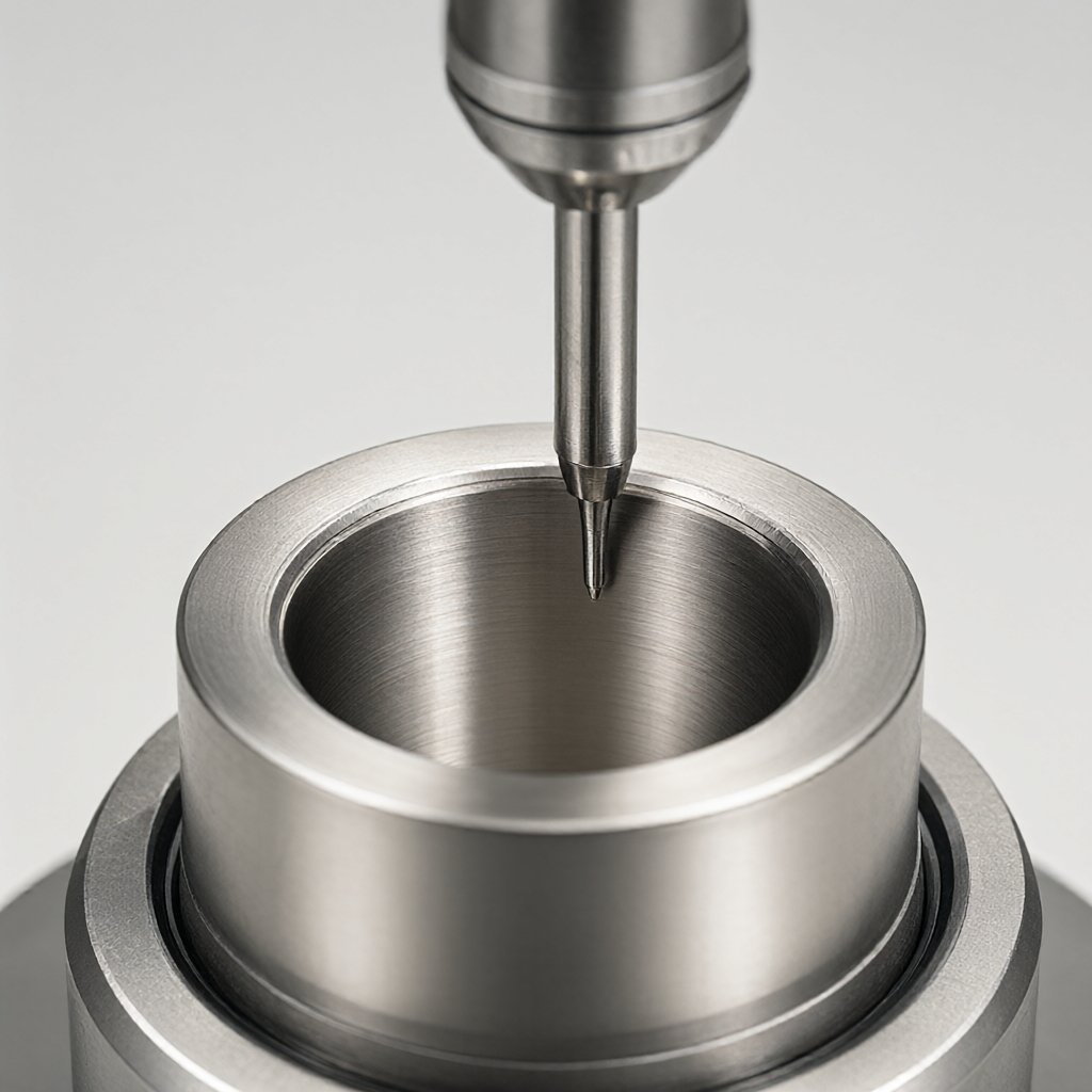
Use a 0.5 mm ball-tip knifedeburring chamfer, angle 15°-30°, feed rate Fz=0.02 mm/rev. Avoid using manual trimming such as files to avoid damaging surface finish and size accuracy.
Q4: Which links do the positioning errors of the five-axis linkage inclined holes mainly come from?
It is suggested to preheat the spindle for 30 minutes before machining, replace the spring clamp with hydraulic expansion fixture, and enable the tool tip radius compensation dynamic update function in CAM.
Q5: How to evaluate whether the supplier has the real five-axis deep hole machining capability?
Request the same material, the same L/D parametersFirst Article Inspection Report, including CMM point cloud data and roughness atlas. Check whether it has constant temperature workshop, pneumatic gauge and tool wear management process. Refer to our surface treatment process instructions to confirm whether the stress relief and polishing process is complete.
Conclusions and recommendations for action
Precision valve coreFive-axis CNC machiningSuccess depends onratio of hole depth to diameterwithtool slenderness ratioFine control, rather than relying solely on the number of equipment. Clarifying L/D limits, tool selection and compensation strategies at the DFM stage can significantly reduce batch risk. If your valve core involves deep holes and slender features with L/D > 3 or S/L > 6, it is recommended to send 3D drawings and material grades. We can provide process path evaluation and rapid quotation based on 72 CNC machine clusters and ±0.01 mm accuracy capability to ensure stable delivery and quality.



