





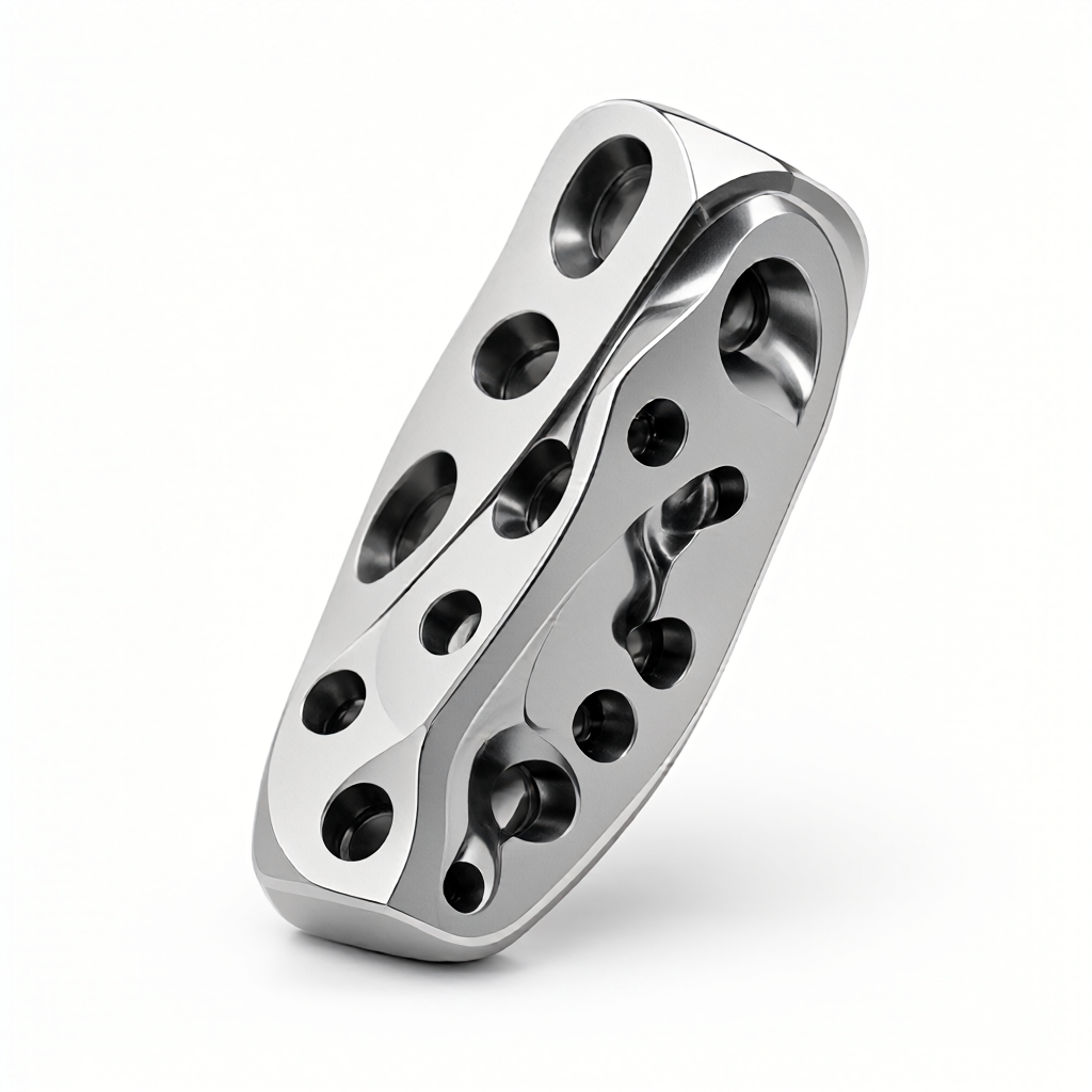
Multi-axis machining of special-shaped parts is the core technology to break through the traditional 3-axis motion limitation and realize one-time clamping of complex curved surfaces and multi-angle features. For R & D engineers and technical procurement, understanding the capability boundary of 3-axis, 4-axis and 5-axis machining in special-shaped parts manufacturing directly determines the design allowance reservation, process route selection and final cost accounting in DFM (Design for Manufacturing) stage. The wrong multi-axis strategy will lead to increased risk of tool interference, low tool utilization, or size out of tolerance due to clamping deformation in batch production. This article will analyze the technical logic of multi-axis linkage machining of special-shaped parts, compare the advantages and disadvantages of different axis number schemes, and give engineering implementation points to help you avoid manufacturing risks in the drawing review stage.
Capability Boundary and Kinematic Basis of Multi-axis Joint Machining of Irregular Parts
Free-form parts usually refer to parts with complex surfaces, deep cavities, inclined holes, or extremely rigid requirements. Traditional 3-axis CNC machining relies on XYZ three straight axes, and the tool can only be fed in normal or radial directions. For features with inclined angles greater than 90 degrees, 3-axis machining often requires multiple fixtures, accumulates positioning errors, and there is a risk of "undercutting"(i.e., the tool cannot reach the bottom of the surface).
4-axis machining introduces A-axis rotation around X or Y axis, mainly for cylindrical shaped parts (such as aviation impeller, automobile steering column) continuous milling. By rotating the workpiece instead of moving the tool, 4 axis can achieve continuous machining of the side wall, reducing the number of clamping times and improving the surface continuity. 5 axis machining increases the B axis or C axis, so that the tool can feed in any direction, realizing the true "one clamping to complete all machining", completely solving the interference problem caused by insufficient rigidity.
- 3-axis linkage: Suitable for flat plate, simple step parts, tool axial direction is always perpendicular to the datum plane.
- 4-axis linkage: Suitable for rotary body, shaft with inclined hole, eliminate lateral feed restriction through A-axis rotation.
- 5-axis simultaneous: Suitable for complex sculpture surface, aviation structural parts, medical implants, tool posture can be adjusted arbitrarily, always avoid interference.
Material selection and DFM recommendations for profiled parts: why 7075 aluminum and 304 stainless steel strategies are different
The thermal conductivity and work hardening characteristics of the material directly affect the cutting parameters of multi-axis linkage. When processing aerospace grade 7075-T6 aluminum alloy, its high thermal conductivity allows the use of higher cutting speeds.(Vc can reach 300-500 m/min), but pay attention to the heat dissipation of the tool. If 5-axis machining is used for its complex thin-walled structure, the influence of the tool overhang length (Overhang) on the rigidity must be considered. It is recommended to control the tool overhang within 1.5-2 times of the rod diameter to avoid vibration ripples during the cutting process.
For 304 stainless steel, its work hardening tendency is serious, and the thermal conductivity is only 1/3 of aluminum alloy. In multi-axis linkage milling deep cavity, the limited chip removal space is easy to lead to the formation of "chip build-up", damage tools and reduce surface finish. At this time, DFM stage should be recommended to increase chip removal grooves or optimize tool paths to avoid closed cavity. If the part has high appearance requirements and complex structure, consider using 4-axis turning and milling compound center, which uses the turning end to complete the body contour and the milling end to complete the porous layout, both ensuring concentricity and optimizing tool life.
3-axis vs 4-axis vs 5-axis: Comparative analysis of processing schemes for special-shaped parts
Part geometry complexity, lot size, and budget are trade-offs before routing decisions are made. The table below compares the performance of the three solutions in a typical profile scenario, based on the operating parameters of a conventional industrial-grade CNC machine.
| Compare Dimensions | 3 axis milling | 4 axis turning/milling | 5-axis simultaneous milling |
|---|---|---|---|
| Applicable geometric characteristics | Flat surface, simple inclined hole, shallow cavity | Solid of revolution, continuous cylinder, sidewall features | Arbitrary complex surface, deep cavity, rigid sensitive parts |
| Clamping times | 2-4 Secondary (need to turn over) | 1-2 Secondary (rotation instead of flip) | 1 time (one-time clamping molding) |
| cumulative positioning error | Higher (multiple tool accumulation) | medium | Very low (baseline unchanged) |
| tool utilization | Lower (shorter blade diameter is limited than tool) | medium | High (to maintain a better angle of incidence) |
| Equipment utilization and cost | Low (long processing time, more stations required) | medium | High (single programming is complex, equipment investment is large) |
| batch consistency | Depending on fixture accuracy, fluctuations are large | Better, especially suitable for shaft parts | Extremely high, especially suitable for precision and complex parts |
From the table, it can be seen that if the main feature of the special-shaped parts is the rotating body (such as pump body, turbine), the 4-axis turning-milling compound is the best solution. If it is a free-form surface (such as robot joint, medical guide plate), the 5-axis linkage can significantly reduce the risk of interference and improve the surface quality. For mass production, even if the initial equipment investment is high, the 5-axis reduces the process merger and quality inspection time, and the comprehensive cost is often lower than that of the 3-axis multi-tool solution.
Cutting Parameters and Tool Path Optimization: Avoiding Interference and Vibration
The core difficulty of multi-axis linkage lies in collision detection and dynamic constraints. Tool Axis Control must be enabled during CAM programming. Common strategies include Down Projection and Ray Project.
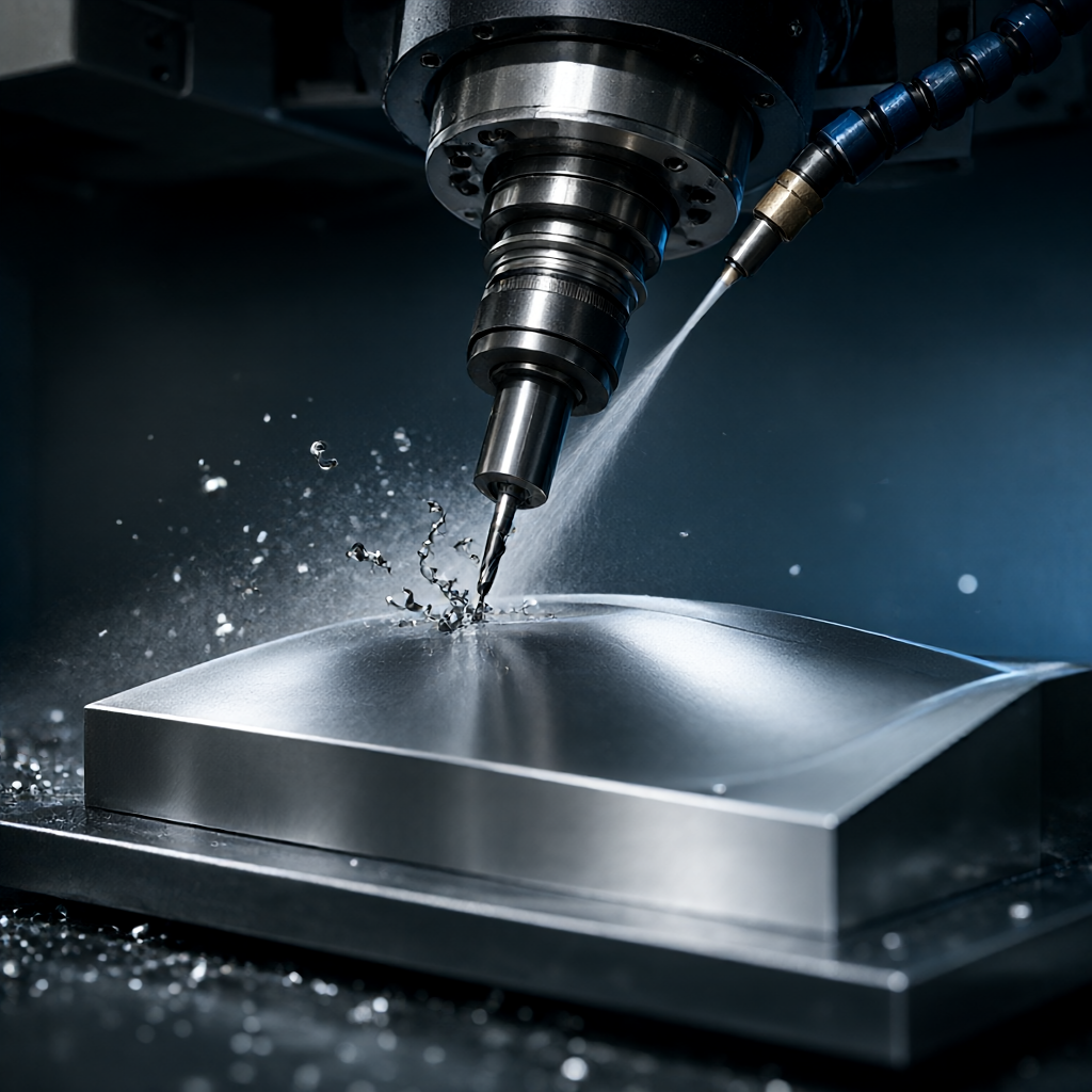
- drop projection: Suitable for most milling scenarios, the tool is advanced to point normal to the workpiece surface, but it is necessary to check whether the bottom holder interferes with the fixture.
- ray casting: Allows you to specify a fixed orientation (e.g. perpendicular to a plane), suitable for machining features parallel to a particular datum, so that the surface texture direction is consistent.
For 7075 aluminum alloy special-shaped parts, it is suggested to adopt "adaptive milling" strategy.(Adaptive Machining) to maintain constant unmachined allowance (usually 0.5-1.0 mm), which stabilizes the cutting load at a tool participation rate of 70-80% and significantly reduces vibration. Feed speed (F) is usually set at 3000-6000 mm/min, depending on tool diameter (D): f = 10-20 D × Z (number of teeth) × RPM. For 5-axis finish milling, it is recommended to reduce the feed to 15-20 D and smooth the surface with the ball cutter end to achieve a surface finish below Ra0.8μm.
Surface treatment and precision inspection: ensure appearance and size double standard
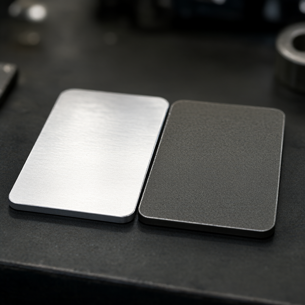
Shaped parts often have both functional and visual requirements. For example, consumer electronics or audio housings, CNC machined bare parts often have milling patterns. If a high gloss or mirror effect is required, the surface treatment process needs to be confirmed at the DFM stage: Anodizing can improve corrosion resistance and color; Blasting can eliminate milling patterns and obtain a matte texture; Plating can enhance conductivity and give metallic luster.
The test strategy needs to be preceded. For 5-axis machining parts, the critical size is often located in deep cavity or inclined surface, which is difficult to be marked by traditional CMM. In this case, optical scanner should be combined (Laser Scanning) Full size comparison, focusing on monitoring Form Deviation. If the tolerance requirement reaches ±0.01 mm, it is necessary to add a thermal compensation module to the CNC program, because long cutting stroke will cause thermal drift of the spindle. Before shipment, 100% critical size inspection should be performed, and CMM inspection reports should be kept to ensure batch consistency.
Common failure modes and engineering workarounds
In the actual combat of multi-axis linkage machining of special-shaped parts, the following three types of failures are the most common, and procurement and engineers need to avoid them in advance:
- tool interference fracture: When 5-axis finishing a narrow space, the tool holder or chuck collides with the workpiece. Avoidance solution: Set the "Tool Lateral Margin" and "Base Tool Lateral Margin" in CAM, and run a no-tool before the first piece is cut. idle walking simulation.
- clamping deformation: Soft materials (such as aluminum alloy) or thin-walled parts are out of round under strong clamping. Avoidance options: use vacuum suction or flexible clamps (Sof clamps), or use 4-axis turning ends for support turning (Live Turning), with spindle side tool holders providing support during machining.
- Surface Chatter: Cutting depth fluctuation caused by tool attitude change when multi-axis linkage. Avoidance scheme: use hard alloy blade, optimize feed rate to avoid resonance zone, and use damping damping cutting fluid if necessary.
How to balance the delivery time and MOQ of irregular parts batch processing?
Usually, 1 sample cycle is about 3-5 working days (excluding programming and DFM analysis). Mass production (500-5000 pieces) If 5-axis automatic loading and unloading is adopted, the delivery time can be compressed to 15-25 days.
Is 5 axis machining more accurate than 3 axis machining?
Not relatively. Accuracy depends on equipment accuracy, thermal control ability and clamping stability. The advantage of 5-axis is that "one-time clamping" eliminates accumulated errors in multiple positioning. For parts with strong rigidity and complex features, 5-axis can maintain higher geometric consistency; for simple flat parts, high-precision 3-axis precision fixtures can also achieve ±0.01 mm tolerance.
How to evaluate the multi-axis machining capability of suppliers?
Ask if the supplier has 5-axis simultaneous interpolation capability (not just inter-axis interpolation), equipment size (e.g., 72 + CNC clusters), and full inspection methods such as 3-D coordinates and roughness meters. Also, confirm that they provide DFM recommendations and FAI processes, which are key to batch consistency.
How much design allowance should be reserved before machining special-shaped parts?
For anodized or plated parts, a plating layer thickness allowance of 0.05-0.1 mm needs to be reserved; for sandblasted parts, a material removal of 0.02-0.03 mm needs to be considered. When designing the wall thickness, if 5-axis processing of deep cavities is required, The minimum wall thickness is recommended to be no less than 1.0 mm, otherwise it will easily lead to processing deformation due to insufficient rigidity, or damage to later surface treatment.
Can engineering plastic special-shaped parts be processed with multi-axis?
Yes. However, it is necessary to change the tool material (it is recommended to use high sharpness carbide or high speed steel), and greatly increase the speed (up to 10000-15000 RPM) to reduce the cutting force and prevent the plastic from melting and sticking to the tool. When machining PEEK or PEI and other high temperature plastics with 5 axes, it is necessary to pay attention to the cooling method. Dry cutting or micro-lubrication (MQL) is usually used to avoid contamination of the surface by water-soluble cutting fluid.
Conclusions and guidelines for action
Multi-axis machining is not a simple equipment stack, but a system engineering covering materials, geometry, tools, paths and inspections. For engineers, it is recommended to clarify the 3/4/5 axis division at the DFM stage; for procurement, attention should be paid to the supplier's process details and batch consistency control capabilities, rather than simply comparing the number of equipment. If you have drawings or 3D models of complex shapes (STEP/IGS format), it is recommended to launch a request for quotation immediately to obtain cutting parameter simulation and DFM optimization suggestions for your specific material to ensure that project nodes and quality objectives are achieved.



