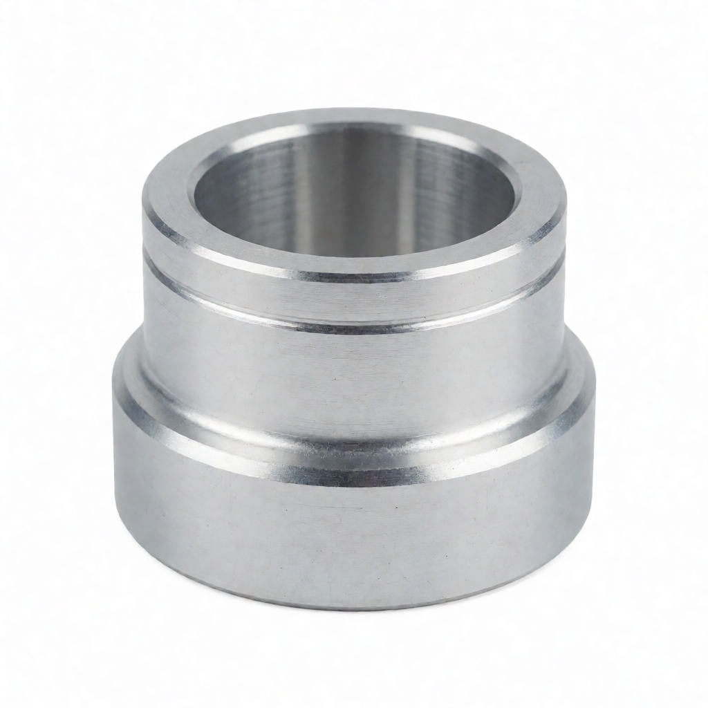
In the manufacturing process of precision aluminum parts, any oversight from material selection to cutting parameters to surface treatment can lead to final product failure or cost explosion. Many engineers in initial design tend to overlook the anisotropic and thermally sensitive characteristics of aluminum alloys (such as 6061, 7075), leading to deformation, surface chatter marks, or hardness non-compliance issues during CNC machining. A deep analysis of common errors in aluminum alloy machining requires combining specific process parameters, inspection standards, and failure analysis to help buyers and R&D personnel mitigate risks at the source. Based on practical production experience, this article outlines typical misconceptions in the entire chain from material procurement to shipment inspection and provides actionable solutions, ensuring that your precision aluminum parts have high consistency, low defect rate, and reliable mechanical properties in mass production.
1. Confusion of Material Grades and Incorrect Temper Selection
Aluminum alloy is not a single material; different grades (such as 6061-T6, 7075-T651) differ greatly in strength, thermal conductivity, and machinability. The most common error is specifying only "aluminum alloy" in the drawing without specifying the exact grade and heat treatment condition (Temper). For example, 6061 has good corrosion resistance and medium strength, suitable for most general structural parts; whereas 7075 has extremely high strength but poor toughness, making it more suitable for aerospace or high-strength transmission components.
Impact of Grade and Temper on Machining Accuracy
If the temper is not specified, the supplier may default to providing the soft condition (O temper or H12), which has low hardness and low cutting resistance, but is prone to deformation and poor dimensional stability; if the design requires high strength, T6 or T651 temper must be specified. T651 temper eliminates micro-cracks and residual stresses caused by machining through re-solution treatment, resulting in higher dimensional accuracy than T6, but at a slightly higher cost. For critical dimensions with a tolerance of ±0.01mm, the material temper must be confirmed; otherwise, subsequent heat treatment may cause part deformation exceeding tolerances.
- 6061-T6: General structural parts, balancing strength and cost, with good corrosion resistance.
- 7075-T6: High-strength structure, but high notch sensitivity; avoid sharp edges and corners.
- 5052-H32: Strong corrosion resistance, commonly used in marine or chemical environments, but lower strength than 6061.
2. Surface Defects Caused by Improper CNC Cutting Parameters
Aluminum alloys have a low melting point and fast thermal conductivity, but an elastic modulus of only about 1/3 that of steel, making them prone to elastic deformation and vibration. If excessive cutting depth (Depth of Cut) or mismatched spindle speed is used, "chatter marks" are easily produced, destroying surface finish (Ra value). Common errors include: spindle speed too low causing the tool to "scrape" rather than "cut" on the workpiece surface; feed rate too high causing chip clogging, leading to secondary cutting and scratches.
Practical Key Points for Optimizing Cutting Parameters
For 6061 aluminum alloy, the recommended spindle speed range is typically 8000-15000 RPM (depending on tool diameter), and the feed rate should be controlled between 300-800 mm/min (high-speed milling). The key principle is: shallow cutting depth, high spindle speed, high feed. If using a large-diameter end mill for rough machining of flat surfaces, the spindle speed should be kept below the critical speed to avoid resonance. For a precision mirror finish (Ra≤0.4μm), the cutting depth should be reduced to 0.05-0.1mm in the finishing stage, and polishing-grade coated tools (such as TiAlN) should be used.
| Defect Type | Possible Causes | Process/Parameter Adjustment Recommendations |
|---|---|---|
| Surface Chatter Marks | Fluctuating cutting forces, tool wear, insufficient machine rigidity | Reduce feed, increase spindle speed (avoid critical speed), use new tools, increase support |
| Surface Burn/Glazing | Accumulation of friction heat, insufficient lubrication, excessive cutting depth | Use high-pressure coolant, reduce cutting depth, optimize chip flute geometry |
| Excessive Burrs | Low feed rate, tool wear, large edge radius | Appropriately increase feed, replace with new tools, use small edge radius |
3. Deformation and Stress Caused by Unreasonable Fixture Design
Aluminum alloy parts have a high coefficient of thermal expansion (approx. 23μm/m·K) and are sensitive to clamping stress. Common errors include using single-point clamping or applying strong C-clamps to thin-walled parts, leading to local dents or springback after stress release, causing dimensional out-of-tolerance. Additionally, if the contact surface between the fixture and the workpiece is not machined flat, stress concentration will occur, affecting machining accuracy.
Core Principles of Fixture Design
For thin-walled aluminum parts, one should ad mit Vakuumsaugnuten oder