

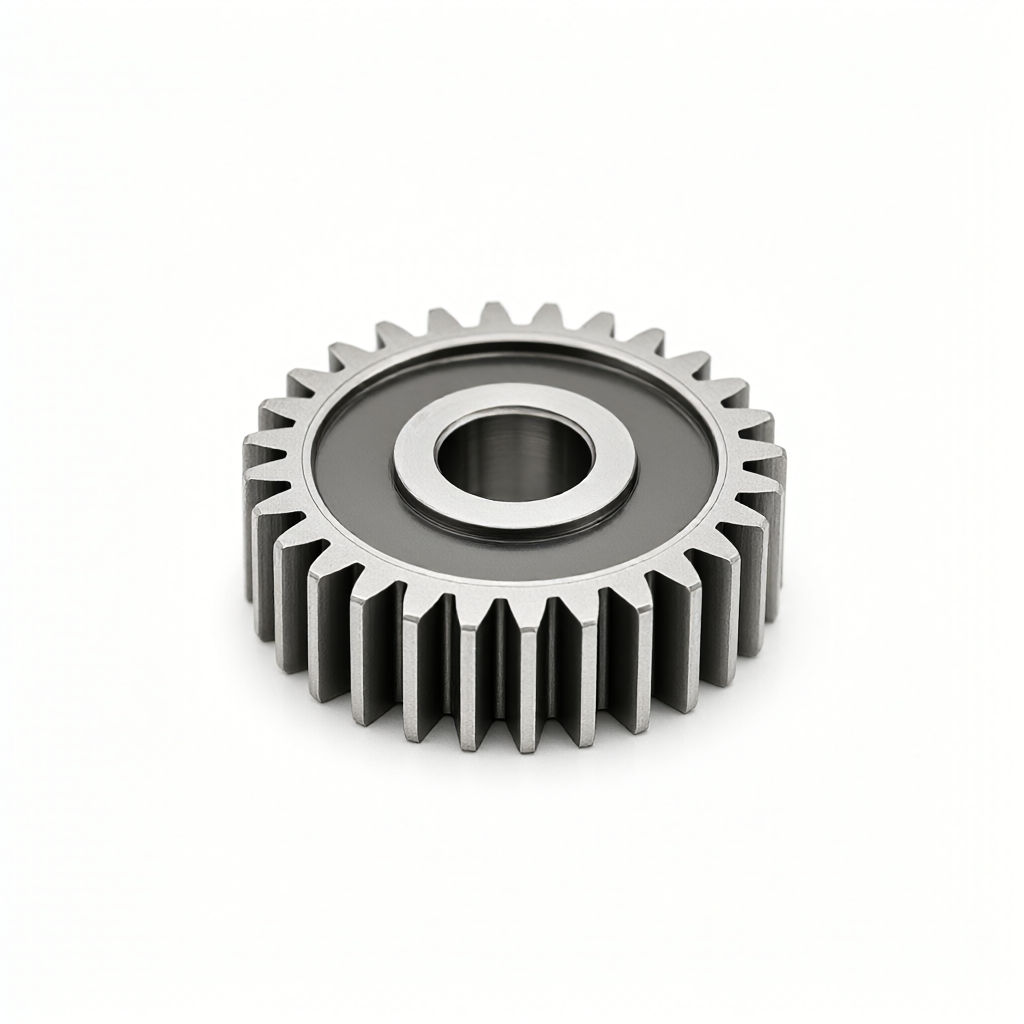
In medical equipment, micro-gears often assume the core transmission task of driving endoscopes, syringe pumps or precision surgical robots. Due to the stringent requirements of reliability, cleanliness and biocompatibility in medical environments, these parts areCNC Machining of Medical DevicesThe difficulty is much higher than ordinary industrial gear. Many purchasers are faced with engineerssmall module gearThis paper discusses how to ensure the disassembly of the system from parameter design, machining path, material selection to acceptance criteria, combining with the experience of precision manufacturing engineering.micro-gearofprofile accuracyConsistency with production helps you quickly identify risk points during the technical evaluation phase and obtain machining solutions that meet medical grade standards.
Specificity and core challenges of miniature gears in medical devices
Different from ordinary industrial gears, gears in medical instruments usually have a module less than 0.5mm and a tooth thickness between 0.3mm and 0.8mm. This extremely small size pairprofile accuracyHigher requirements are put forward: the roughness of the tooth surface usually needs to reach Ra0.4μm or less, and there must be no machining burrs, microcracks or metal residues on the surface. In addition, medical parts often need to operate in a small space for a long time without failure. Any small defects on the tooth surface may spread rapidly under high frequency vibration, resulting in transmission jamming or excessive noise.
Another challenge that is often overlooked is the material. Medical grade stainless steel (e.g. 316L, 17-4PH) or titanium alloys have poor cutting performance, tool wear is fast, and if the machining parameters are not appropriate, residual tensile stress is easily generated at the root, affecting fatigue life. Therefore, the process path design must place "stress control" as much priority as "size accuracy."
Modulus, accuracy class and tolerance design of small modulus gear
Before customization, the first step to avoid subsequent rework is to define the accuracy class of the gear. According to ISO 1328-1, medical micro gears are usually selected with accuracy classes 7 to 9. Class 7 is suitable for high speed precision transmissions (e.g. endoscope zoom rings) and Class 9 is suitable for general drive mechanisms (e.g. electric syringe pumps).
The choice of modulus (m) directly affects the root stress and bending resistance. For micro gears with m=0.25mm, it is recommended to control the root fillet radius above 0.08mm to alleviate stress concentration. The following table shows the recommended tolerance control strategy for different moduli:
| Modulus Range (mm) | Recommended accuracy level | Tooth profile deviation (μm) | surface roughness requirements | Critical Failure Mode Risk |
|---|---|---|---|---|
| 0.1 - 0.3 | 7-8 step | ≤ 3 | Ra0.2 - Ra0.4 | Tooth surface abrasion, fretting wear |
| 0.3 - 0.5 | 8-9 step | ≤ 5 | Ra0.4 - Ra0.8 | root fatigue crack |
| 0.5 - 1.0 | 9 grades | ≤ 8 | Ra0.8 | Plastic deformation of tooth surface |
In tolerance design, special attention should be paid to the "cumulative error" effect. When multiple micro-gears are connected in series, the pitch deviation of a single gear will be amplified along the transmission chain. It is recommended to introduce "conjugate error compensation" in the design stage to ensure that the mesh clearance is between 0.02mm and 0.05mm, which ensures lubrication and avoids impact.
Precision CNC machining paths: key processes to avoid tooth surface defects
toCNC Machining of Medical DevicesFor micro gears in the middle, it is often difficult to balance efficiency and surface quality with ordinary three-axis milling. It is recommended to use 4-axis or 5-axis linkage machining path to reduce tool lateral clearance through "swing milling" or "slotting" strategy to ensure tooth surface consistency.
- Roughing:Using a carbide end mill with a diameter of 0.8mm - 1.2mm, the "cycloid" strategy is divided into 4-6 cuts to 0.1mm to control cutting heat and residual stress.
- Finishing:Replace 0.4mm - 0.6mm spiral end mill, feed speed control at 300- 500mm/min, spindle speed 18000- 24000rpm. At this time, be sure to turn on the "forward milling" mode to avoid tooth surface tearing caused by reverse milling.
- Root strengthening:Use a "smooth" track at the root fillet to avoid tool marks. For titanium alloys or stainless steels, it is recommended to perform a "low temperature tempering" treatment after finishing to eliminate residual tensile stress.
Surface finish is a core acceptance criterion for medical gears. By using micro-crystalline superabrasive (CBN) tools in the finishing stage, surface roughness can be stably controlled to within Ra0.4μm without obvious cutting lines. This detail should be requested from suppliers for "lot roughness distribution curves" rather than single averages during procurement evaluation.
Material selection and surface treatment: balance strength and biocompatibility
Materials are the cornerstone of gear life. For most medical transmissions,316L Stainless SteelBecause of its excellent corrosion resistance and solderability become the first choice; if you need high strength, choose17-4PH precipitation hardened stainless steelFor weight-sensitive surgical robots, considerTitanium alloy (Ti-6Al-4V). Engineering plastics such as PEEK or PTFE are lightweight and self-lubricating, but they need to be used with metal substrates to cope with higher loads.
In terms of surface treatment, chromate passivation is strictly prohibited for medical parts. The combination of "electrolytic polishing + passivation" is recommended: electrolytic polishing can reduce the surface Ra to less than 0.2μm, significantly improving the pitting resistance; passivation can form a dense oxide film to enhance biocompatibility. For consumer medical equipment with extremely high appearance requirements (such as home monitors),"microblasting + anodization" process can also be added to achieve batch consistency with high bright surface and no scratches.
Inspection methods, failure mode avoidance and acceptance criteria
The acceptance of medical grade gears cannot rely solely on "coordinate measurement". Since the tooth surface is a complex free-form surface, it is recommended to adopt the "optical image measurement + laser interferometer" combination scheme:
- Tooth profile detection:Scan the tooth surface with laser profilometer and compare the theoretical envelope line. The deviation shall comply with the corresponding grade requirements of ISO 1328.
- Surface integrity:Penetrant inspection or magnetic particle inspection is used to check root microcracks. For batch products,"visual AI inspection" can be introduced instead of manual inspection to ensure 100% complete inspection without omission.
- Operation test:500 hours of continuous operation under simulated operating load, monitoring noise (normally required< 45dB)与温升(< 35°C)。
Common failure modes include "tooth surface scuffing" and "early pitting". Scuffing is mostly caused by improper lubrication or excessive tooth surface roughness, and a "lubrication test report" should be mandatory for acceptance. Pitting is related to indentation on the surface of the material and can be avoided by "Rockwell hardness uniformity" sampling. In the DFM (design for manufacturability) stage, it is recommended that suppliers intervene early to point out sharp corners, thin walls and other risk structures and provide alternatives.
FAQ: Frequently Asked Questions about Micro Gear Machining
How much can the minimum module of CNC machining of micro gears be achieved?
With the support of precision equipment, the minimum machinable modulus is about 0.1 mm. However, when it is lower than 0.15 mm, tool wear and tool yield effect will have a significant impact.profile accuracyIt is suggested to optimize the tool path or use the "powder metallurgy forming + fine grinding" scheme to reduce costs and improve stability.
How to ensure consistent gear surface finish in mass production?
The key lies in "first article confirmation" and "process inspection." The first article in each batch needs to pass full size inspection with three-coordinate and roughness meters, and the processing parameters are locked after passing the inspection. During the production process, the surface Ra value is sampled every 50 pieces to ensure that the deviation is within ±0.05μm, thus ensuring batch consistency with a high-gloss surface and no scratches.
What special treatments are needed after machining medical grade stainless steel gears?
"Electropolishing" and "chromium-free passivation" are required. Electropolishing removes surface microcracks and tool marks, and passivation forms a uniform oxide film. After treatment, a "salt spray test"(usually 96-720 hours) is required to verify that the corrosion resistance meets biomedical standards.
How does the root fillet design affect fatigue life?
The fillet radius directly determines the stress concentration factor. For small module gears, a fillet radius R ≥ 0.1m (m is the module) is recommended. A fillet that is too small can significantly reduce the bending strength and increase the risk of early tooth breakage. This parameter should be listed as a Critical Control Item (CTQ) in the DFM review.
How long is the lead time for proofing and production?
Proofing cycle is usually short, can cooperate with the project node production scheduling. In terms of mass production, relying on 72 CNC equipment cluster (including 3/4/5 axis machining center, walking machine), the conventional batch order can achieve rapid delivery of mass production within 15-25 days. The specific delivery time shall be calculated separately according to the complexity of the tooth surface and surface treatment requirements.
Conclusions and recommendations for action
The machining of micro gears in medical devices is a comprehensive test of precision, reliability and biological safety. Failure modes such as tooth surface scratch and fatigue fracture can be effectively avoided through reasonable selection of modulus, adoption of 4/5-axis precision machining path, strict implementation of "electrolytic polishing + passivation" surface treatment, and cooperation with optical inspection and operation test. As a purchaser or engineer, it is recommended that the supplier be provided with a complete tolerance analysis and DFM requirement early in the project, requiring that they provide a CMM and Roughness Meter based inspection scheme, rather than relying on visual acceptance alone.
if you havesmall module gear, or need to evaluate the processing feasibility of specific materials (such as titanium alloy, PEEK), please send us the drawings and technical requirements, and we will provide process path suggestions and accurate quotations based on actual conditions.