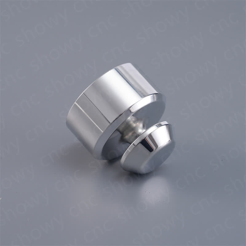


Why do robot flanges need high-precision CNC milling and flatness control
The flange of manipulator arm is the key load-bearing part connecting the end effector or the next joint, which directly bears the torque, axial force and lateral load. If the flatness of flange surface is out of tolerance or the coaxiality of stop is insufficient, rigid interference will occur during assembly, and it is easy to cause uneven bolt preload, fretting wear and even structural failure under long-term operation. High-precision CNC milling is the core technology to control the geometric accuracy of such features. Through multi-axis linkage and rigid clamping, tool path deviation and thermal deformation can be effectively suppressed, and the flatness of flange surface can be controlled in the micron range to ensure the positioning repeatability of robot arm in high-speed motion.
Analysis of key geometric parameters: flatness, coaxiality and surface roughness
Flatness is the most basic geometric parameter in robot flange design. For standard ISO 9409-1-50 or 80 interfaces, flatness is usually required to be no more than 0.02mm, and some precision servo drive end interfaces are even required to be ≤0.01mm. Flatness errors can lead to reduced contact area ratio of mating surfaces, local pressure surges, accelerated aging of seals (if present) or crushing of joint surfaces.
The alignment accuracy of the mounting reference surface is controlled by the concentricity of the stop. If the concentricity deviation between the stop step surface and the sealing surface exceeds 0.05mm, the flange will be inclined during assembly, resulting in asymmetric force on the through-bolt, causing stress concentration. In addition, the surface roughness of the sealing surface directly affects the sealing reliability. Generally, Ra values should be controlled between 0.8μm and 1.6μm. If vacuum environment or anti-drip structure is involved, it should be ground to Ra≤0.4μm, or even polished to mirror effect.
Material selection and mechanical properties match: steel, aluminum and engineering plastics
The material selection of the robot arm flange depends on the load requirements and weight reduction strategy. In high strength scenarios, 42CrMo4 quenched and tempered steel or 40CrNiMoA is usually selected. After quenching and tempering, the hardness can reach HRC28-32. Both high strength and toughness are suitable for withstanding high frequency alternating loads. The lightweight scene is mostly 7075-T6 aluminum alloy or 6082-T651 aluminum alloy, the density is only 1/3 of steel, but pay attention to the creep characteristics of aluminum alloy, the flatness may change slightly due to stress release under long-term static load, and the aging treatment process needs to be added after processing.
- 42CrMo4 quenched and tempered steel:Tensile strength ≥950MPa, suitable for high torque robot arm, but high cutting hardness, tool wear fast, need to use carbide tools and optimize cutting parameters.
- 7075-T6 aluminum alloy:Tensile strength ≥570MPa, easy to process, good finish, suitable for medium and low load robots, low requirements for tools, high processing efficiency.
- PEEK Engineering Plastics:It is used to isolate insulation parts in some light-load collaborative robots. Attention should be paid to thermal deformation during processing, and low-temperature cutting or micro-lubrication should be adopted.
Comparison of precision machining solutions: three-axis milling and five-axis milling compound
For different structural complexity of robot arm flange, the choice of machining scheme directly determines the accuracy and cost. Simple disc flange can be milled by three-axis vertical machining center, while flange with inclined cone, special-shaped stop or thin-walled structure must be introduced into five-axis machining or turning-milling compound process.
| processing scheme | Applicable flange type | flatness control capability | main advantage | limitations |
|---|---|---|---|---|
| 3-axis CNC milling | Standard disc, straight stepped flange | Stable up to 0.01mm | High equipment penetration, simple tool path, high machining efficiency | Inclined conical surface cannot be machined, thin-walled parts are easy to vibrate, and secondary clamping is required. |
| Five-axis simultaneous milling | Flange with special-shaped spigot and inclined sealing surface | Stable up to 0.005 - 0.01mm | One-time clamping to complete multi-surface machining, avoiding datum conversion errors, suitable for complex surfaces | Complicated programming, high risk of tool interference, high rigidity requirements for machine tools |
| lathe-milling combined machining | Rotating body flange, flange with radial hole system | Stable up to 0.005mm | Turning to ensure the run-out of the outer circle, milling to complete the plane and hole system, process concentration, good concentricity | Not suitable for large diameter non-rotating structure, equipment occupies a large area |
For high-consistency batch production, turn-milling compound is often superior to pure five-axis milling, because the coaxiality of rotary body features processed by lathe is naturally superior to milling machine. For flanges with asymmetric seal grooves or special angles, five-axis linkage is a reliable solution to maintain datum consistency and avoid accumulated errors.
Practical points: clamping deformation control and tool path optimization
Clamping deformation is the primary source of flatness out-of-tolerance. Thin-walled arm flanges (wall thickness