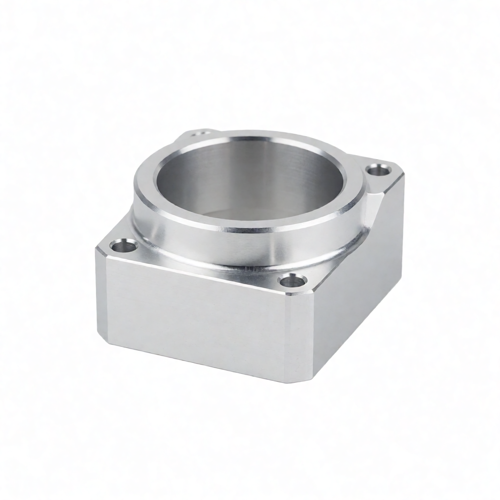
Core Value and Technical Key Points of CNC Finish Machining Before Anodizing
In the precision aluminum parts manufacturing process, CNC finish machining before anodizing is a critical step to ensure the performance and aesthetic quality of the final product. Many engineers and procurement specialists often wonder: why not just anodize rough-machined parts directly? The answer lies in the anodizing film thickness (typically 5–25μm), which significantly alters part dimensions. If tolerances are not properly controlled in the initial stages, anodizing can easily lead to assembly failures. This article provides an in-depth analysis of the necessity of CNC finish machining prior to anodizing, including process parameter control, material selection, and acceptance criteria, helping you build a reliable quality loop.
Dimensional Compensation Principles: The Impact of the Anodizing Film on Final Tolerances
Anodizing generates a dense Al₂O₃ film on the aluminum surface through an electrochemical method. This film grows in both directions—into the substrate and outward—but external growth predominates. For internal surfaces such as holes and slots, the anodizing film reduces the hole diameter; for external surfaces, it increases the diameter. This dimensional change is not uniform and is influenced by current density, electrolyte temperature, and concentration, with a typical variation range of 0.5–2μm/mm.
Key Parameter: Calculating Pre-Anodizing Allowances
- External Surfaces: Total allowance = (Anodizing film thickness × 2) + Machining allowance. For example, if the required post-anodizing outer diameter is φ10.00mm with a film thickness of 10μm, the CNC finish-machined diameter should be φ10.02mm (10.00 + 2×0.01).
- Internal Surfaces: Allowance = (Anodizing film thickness × 2). For example, if the required post-anodizing hole diameter is φ5.00mm with a film thickness of 10μm, the finish-machined hole diameter should be φ4.98mm.
- Key Reminder: Allowances must be based on specific anodizing processes (e.g., sulfuric acid/oxalic acid) and film thickness requirements, not generic values. It is recommended to confirm the actual film thickness variation range (±5μm) with the anodizing plant and include compensation in the CNC programming.
Surface Roughness Control: Preventing Defects from Being "Amplified" After Anodizing
The anodizing film replicates the substrate's surface topography completely. If the surface roughness after CNC finish machining has a high Ra value (e.g., Ra3.2μm), the Ra value will remain nearly unchanged after anodizing, or even appear rougher due to the micro-porous structure of the film layer. For appearance-critical components with high finish requirements (such as consumer electronics enclosures and audio components), Ra must be controlled to 0.8–1.6μm during the CNC stage to meet visual and tactile standards after anodizing.
Process Implementation Paths for Different Ra Values
- Ra3.2μm: Standard 3-axis milling with carbide tools, cutting speed Vc=300-400m/min, feed per tooth fz=0.05-0.1mm.
- Ra1.6μm: Finish turning/milling using coated carbide or CBN tools, reducing feed to fz=0.03-0.05mm with a small depth of cut (ap≤0.5mm).
- Ra0.4-0.8μm: Requires a two-step process of semi-finishing and finishing, or high-speed milling (Vc>500m/min), ensuring tool sharpness and rigidity.
Impact of Material Selection and Machinability on Anodizing Performance
Not all aluminum alloys are suitable for high-quality anodizing. Casting aluminum with high silicon and iron impurities (such as A380) results in a whitish film layer with poor adhesion after anodizing. High-purity wrought aluminum alloys (such as 6061-T6, 7075-T6, 5052) produce uniform film layers with excellent corrosion resistance. During CNC machining, the material grade directly affects cutting parameters and tool selection, which in turn impacts surface quality.
| Alloy Grade | Typical Applications | CNC Machining Challenges | Anodizing Suitability |
|---|---|---|---|
| 6061-T6 | Structural components, mechanical brackets | Machining is relatively easy, but slight built-up edge tendency | Excellent, dense film layer, uniform coloring |
| 7075-T6 | Aerospace, high-strength components | High hardness, rapid tool wear, requires significant cooling | Excellent, but stress corrosion must be monitored |
| 5052-H32 | ;Containers, cosmetic parts | High toughness, prone to chatter, requires high rigidity | Excellent, optimal appearance after anodizing |
| 2024-T4 | High-strength structural components | Prone to chatter during cutting, surface easily deforms | Moderate, oxide film tends yellow, slightly weaker corrosion resistance |
Synergistic Control of Surface Morphology and Geometric Precision
In addition to dimensions and roughness, CNC finishing must ensure part flatness, concentricity, and profile. During anodizing, parts in the electrolytic cell are affected by uneven current distribution, resulting in thicker oxide films on raised areas and thinner films in recesses. If residual stress concentrations or shape distortions exist after CNC machining, defects will be visually amplified after anodizing. For cosmetic parts, we recommend adding a vibration stress relief or static stress annealing step after CNC machining to minimize substrate deformation before anodizing.
Recommended Key Geometric Tolerances
- Flatness: ≤0.02mm/m to avoid the "warping" illusion after anodizing.
- Concentricity: ≤0.05mm to prevent hole/shaft fit failure.
- Profile: Per drawing requirements, with critical mating surfaces controlled within 0.03mm.
Process Synergy Before and After Anodizing: Full-Chain Control from Programming to Inspection
Successful anodizing is not a standalone process, but the result of synergy among CNC machining, anodizing, and inspection. Our production process ensures seamless integration at every stage:
- Incoming Material and DFM Review: Engineers assess anodizing impacts based on drawings, proposing CNC allowances, deburring requirements, and clamping strategies.
- CNC Finishing: 72 machines (including 3/4/5-axis machining centers) perform two-process operations. First articles undergo full inspection via CMM and roughness meters to confirm that Ra and dimensions are within compensation ranges.
- Pre-Anodizing Cleaning: Thorough removal of cutting oil and chips to prevent oxide film delamination caused by inclusions.
- Outgoing Full Inspection: Post-anodizing dimensional re-measurement (accounting for film thickness), film thickness testing (1μm precision), salt spray testing (≥24h without corrosion), and visual inspection.
FAQ: Common Questions About CNC Finishing Before Anodizing
Does anodizing change part dimensions? How is this compensated?
Yes. The oxide film grows outward, increasing external diameters and reducing internal diameters. Compensation method: In CNC programming, add twice the film thickness to external surfaces and subtract twice the film thickness from internal surfaces. Specific values must be confirmed with the anodizing plant regarding their process film thickness variation (e.g., 10μm±5μm), and CNC tolerances must be set within this range.
Can a surface with Ra0.4μm after CNC finishing be anodized?
Yes, and the effect is excellent. The mirror finish of Ra0.4μm will be retained after anodizing, presenting a high-gloss appearance. Note, however: the micro-porous structure of the oxide film may slightly increase the Ra value (to around Ra0.8μm). Therefore, if Ra≤0.4μm is required after anodizing, the CNC stage must be controlled to Ra0.2μm.
Why is direct anodizing of rough-machined parts (Ra12.5μm) not recommended?
After anodizing rough-machined surfaces, the oxide film cannot mask tool marks and chatter marks, amplifying cosmetic defects. Additionally, micro-cracks in the rough substrate will propagate along the oxide film, reducing corrosion resistance. For cosmetic parts, CNC finishing to Ra≤1.6μm is the minimum threshold.
Which part areas are unsuitable for anodizing?
Sealing surfaces, precision mating surfaces (such as bearing bores and O-ring grooves), and electrical contact points. The oxide film is an insulator and impedes conductivity; moreover, film thickness variation affects mating clearances. These areas typically require "anti-anodizing" markings, with tape protection during anodizing or separate conductive anodizing (chromic acid washing).
What is the maximum storage time between CNC machining and anodizing?
Storage of ≤72 hours is recommended, with anti-rust oil application and moisture-proof packaging. Aluminum parts easily develop surface corrosion white spots (white rust) in humid air, requiring thorough cleaning before anodizing. Prolonged storage will result in the oxide film covering corrosion products, leading to adhesion failure. Batch production typically uses continuous flow operations of CNC-anodizing-inspection to minimize waiting time.
Conclusion: Treat Anodizing as a Post-Process to CNC Finishing
Anodizing is not merely "surface treatment," but an "amplifier" of CNC finishing quality. Only by strictly controlling dimensional compensation, surface roughness, material selection, and geometric precision at the CNC stage can high-reliability, high-cosmetic-quality aluminum parts be produced after anodizing. If you encounter post-anodizing dimensional out-of-tolerance, cosmetic defects, or film delamination in batch production, the root cause often lies in the CNC stage.
If you have precision machining needs for aluminum parts prior to anodizing, please send drawings and technical requirements to our engineering team. We will provide DFM suggestions, CNC process plans, and anodizing allowance calculations within 24 hours, while simultaneously confirming batch delivery times (15-25 days) and inspection plans. From programming to outgoing full inspection, we ensure every product meets your assembly and cosmetic standards.