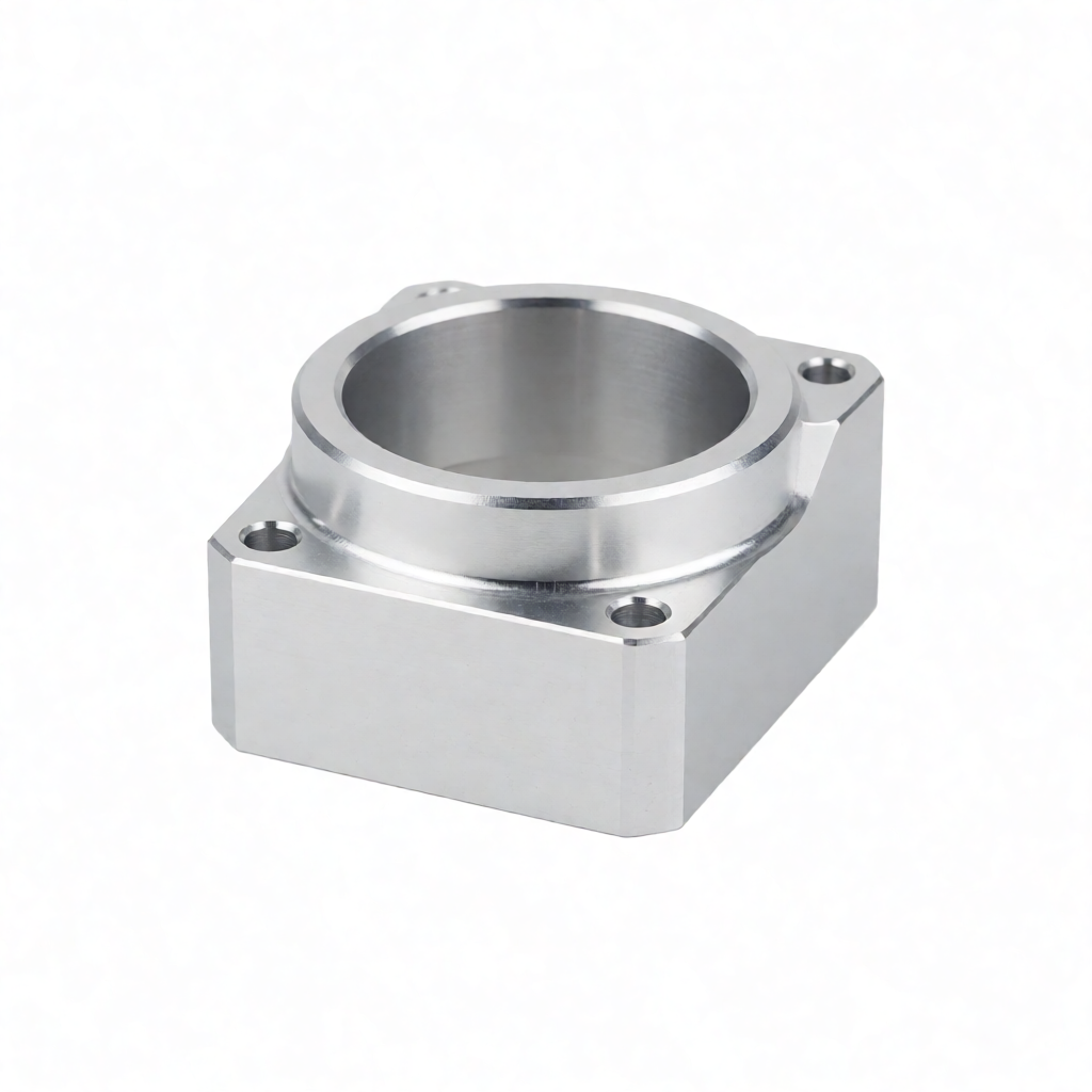
Root Cause Analysis of Stress Release and Dimensional Drift in Aluminum Alloy CNC Machining
In the mass production of precision aluminum alloy components, stress deformation and post-machining dimensional drift are two core failure modes. These issues typically manifest within 24 to 72 hours after machining is complete, causing workpiece warping, flatness out-of-tolerance, or bore diameter changes, thereby directly compromising lot consistency. For engineers and procurement teams working with mainstream aluminum alloys such as 6061, 7075, or 5052, understanding the distribution mechanism of residual stress within the aluminum is a prerequisite for defining a qualified process route and locking down the tolerance budget. Aluminum alloys accumulate high levels of internal residual stress during the casting or extrusion stage; once surface material is removed through milling or turning, the stress equilibrium is disrupted, and deformation ensues.
Stress Characteristics of Cast and Extruded Aluminum
Cast aluminum parts (such as ADC12 and A380) exhibit grain boundary segregation and porosity internally, resulting in uneven stress distribution and a high susceptibility to local collapse after machining. Extruded profiles (such as 6061-T651) possess directional residual stress along the axial axis due to differences in cold aging treatment, making them prone to warping when cut at the ends. Understanding these material characteristics is the first step in controlling deformation.
Cutting Heat and Tool Wear Exacerbating Drift
Aluminum alloys have high thermal conductivity (approx. 200 W/m·K); during high-speed cutting, chips carry away significant heat, yet the rising temperature at the tool tip still induces localized thermal deformation in the workpiece. As the major cutting edge of the tool wears, cutting forces increase, enhancing the squeezing effect on thin-walled structures, which leads to minor tool deflection and elastic recovery deviations. These two factors compound to form the dynamic source of post-machining dimensional drift.
Stress Release Behavior and Machining Strategies for Different Aluminum Alloys
Different aluminum alloy grades have varying aging states, grain sizes, and heat treatment histories, which directly determine the magnitude of residual stress and its release pathways. Blindly applying a single set of process parameters is the root cause of dimensional loss of control in many factories. Below are the characteristic differences and coping strategies for three commonly used grades:
- 6061-T6: Excellent overall performance, though the T6 state contains moderate internal hydrogen levels and aging stress. For milling, a "roughing–semi-finishing–finishing" three-step approach is recommended, with an intermediate waiting period of more than 2 hours to allow initial stress release before finishing key surfaces.
- 7075-T651: High-strength aerospace-grade material with high yield stress and large residual stress. It must undergo double treatment of natural aging and artificial aging, or be subjected to stress-relief aging furnace treatment after rough machining (120±5°C, 4 hours).
- 5052-H32: Medium-strength corrosion-resistant aluminum, commonly used for sheet metal or thin-walled parts. Although it has a high elastic modulus, thin-walled parts are susceptible to chatter. It requires increased feed rates, reduced cutting speeds, and shortened tool holder overhang ratios to avoid tool deflection on thin walls.
For lightweight materials such as engineering plastics or magnesium alloys, which have large coefficients of thermal expansion, finishing and inspection must be completed in a constant-temperature workshop. The differences in stress release curves among different grades dictate that we must "adapt the strategy to the material."
Process Path Comparison: Rough-Finish Separation vs. Stress-Relief Aging
In mass production, the core to resolving stress deformation lies in the design of the process path. Should one choose the "one-pass" rapid milling approach, or invest time in "roughing-finishing separation + aging"? The table below provides a quantitative comparison of two mainstream solutions across three dimensions—cycle time, cost, and dimensional retention rate—to help procurement and process engineers make quick decisions:
| Dimension | Scheme A: Integrated Rough-Finish Rapid Milling | Scheme B: Rough-Finish Separation + Stress-Relief Aging | |
|---|---|---|---|
| Applicable Scenarios | Non-critical dimensions, appearance parts, solid structures with wall thickness ≥5mm | Critical hole locations, flatness requirement ≤0.02mm, thin-walled or high length-to-diameter ratio structures | |
| Machining Cycle | Short; single-part cycle approx. 45 minutes, suitable for rapid delivery | Long; total single-part cycle approx. 8 hours (including aging wait time), not suitable for urgent insert orders | |
| Equipment Dependency | Standard 3-axis/4-axis machining centers are sufficient | Requires supporting aging furnaces and CMM inspection equipment, with high requirements for constant-temperature workshop control | |
| Dimensional Retention Rate (after 24h) | Approx. 85%-90% for standard structures; critical holes easily exceed tolerance ±0.03mm | Can reach over 98% for critical structures; tolerance stable in | within ±0.01mm |
| Hidden costs | High scrap rate, increased post-process finishing or fitting costs | High time cost and slow inventory turnover, but excellent consistency in mass production |
The conclusion is: for appearance parts or low-precision structural components, Option A should be prioritized to ensure delivery schedules. However, for precision components involving assembly interference, sealing surfaces, or air tightness, Option B must be adopted, using stress-relieving treatment to "freeze" internal stresses and secure long-term dimensional stability.
Tool Selection and Cutting Parameter Optimization: Blocking the Source of Deformation
Beyond the process route, tool selection and cutting parameters play a decisive role in controlling tool deflection and springback. Because aluminum alloys have low cutting forces, they are highly susceptible to "tool pull-out" or nose indentation, leading to local plastic deformation. The following is an optimization checklist for parameters in precision machining of aluminum alloys:
Sharp Tools and Coating Strategies
It is recommended to use carbide or high-speed steel tools with sharp edges and no rounding (Sharp Edge Prep). For aluminum alloys, prioritize aluminum-specific coatings (such as TiCN or TiAlN) to reduce frictional heat and prevent aluminum chip adhesion to the cutting edge.
Parameter Settings and Rigidity Constraints
- Spindle Speed: Set conventional milling at 8000-15000 rpm; thin-walled parts can be increased to 15000-18000 rpm, utilizing the "small tool, high speed" strategy.
- Depth of Cut and Feed: Rough machining depth of cut should not exceed 1mm; for finishing (last 50μm stock), control depth of cut to 0.1-0.2mm and increase feed rate to 0.15-0.3 mm/rev to avoid the cutting edge "biting" into the material.
- Tool Holder Rigidity: Select high-rigidity tool holders and short tools; strictly control the overhang ratio (holder length/tool diameter) to within 5:1. Thin-walled parts require tool body support.
By optimizing the cutting system, not only can surface finish be improved (easily achieving Ra0.4μm), but micro-deformation and dimensional drift of the workpiece caused by excessive cutting forces can be cut off at the mechanical source.
Workholding Deformation Control: From Fixture Design to Force Simulation
Workholding deformation in machining is an invisible source of stress. Aluminum alloy materials are relatively soft; if the clamping force is slightly too high, thin-walled structures will experience tool deflection or clamping marks; if the clamping force is insufficient, the workpiece may fly out during high-speed rotation. Quantitative management of clamping forces is the baseline for precision mass production.
Application of Vacuum Suction and Spring Collets
For sheet parts with holes or large flat surfaces, prioritize using vacuum suction fixtures to distribute suction force evenly and avoid local crushing. For rotary bodies, design self-centering spring collets or flexible expansion sleeves to provide gentle and adjustable radial support.
Process Datums and Force Analysis
Before programming, stress distribution under clamped conditions must be simulated via Finite Element Analysis (FEA). Identify the point of maximum stress and design the fixture to add targeted support at that point. Simultaneously, during first-article inspection, mark the dimensional compensation values after stress release on the fixture. When batch machining, strictly replicating the first-article clamping state is the ultimate defense against batch-to-batch dimensional drift.
Inspection and Acceptance System: How to Identify and Control Dimensional Drift
The end of machining does not mean the product is qualified; dimensional drift is a dynamic process over time. Relying solely on online probing (probes) on the machine cannot identify deformations caused by stress release. A mature aluminum alloy CNC quality acceptance system must include the following four stages:
Thermal Soaking and Full-Dimensional Sampling
After finishing and removing from the line, the workpiece must be allowed to rest for no less than 24 hours in a constant-temperature environment of 20±2°C to allow internal residual stresses to fully release. Subsequently, use a Coordinate Measuring Machine (CMM) for full-dimensional sampling inspection, ensuring 100% coverage of key tolerances such as flatness, concentricity, and hole distance.
Surface Roughness and Microscopic Inspection
Use a contact roughness tester to sample inspect major appearance surfaces, with the acceptance standard locked at Ra0.4μm or less. Simultaneously, use a 10x magnifying glass or a visual inspection system to check for embedded aluminum chips, tool breakage marks, and surface defects before anodizing or coating. Only batches that pass the resting re-inspection can proceed to the surface treatment process; otherwise, prior-stage stress deformation will be fully exposed and amplified by subsequent processes.
Frequently Asked Questions (FAQ)
Why did the outer diameter of an aluminum part shrink by 0.02mm after 48 hours of resting post-finishing?
This is typically caused by incomplete release of residual stresses. It is recommended to extend the resting time to more than 72 hours, or add a stress-relieving aging process between the rough and finishing stages, and re-verify the first-article compensation values.
In mass production, how to ensure consistent surface finish across different batches of aluminum parts?
The key lies in tool life management and process locking. Establish a tool life monitoring ledger; every time a tool is changed, the wear on the major cutting edge must be re-checked. Simultaneously, lock the cutting parameters on 3-axis/4-axis machining centers to prevent operators from arbitrarily adjusting feed rates and speeds based on experience, thereby stabilizing surface roughness within Ra0.4μm.
If the customer's drawing specifies a tolerance of ±0.01mm, is 5-axis machining mandatory?
It is not strictly mandatory; the decision primarily depends on the structural complexity and interference requirements. If critical dimensions are located on thin-walled surfaces or in multi-plane spatial positions, 4-axis or 5-axis machining centers can complete multi-face machining in a single setup, minimizing datum shifts and accumulated error. This makes them the preferred solution for achieving a ±0.01 mm tolerance. For simple bodies of revolution, high-end CNC turning is sufficient.
Which surface treatment best preserves dimensional stability after precision machining of aluminum alloys?
We recommend Micro-Arc Oxidation (MAO) or low-temperature hard anodizing. Compared to high-temperature black oxide or conventional anodizing, these processes induce minimal thermal deformation. Additionally, highly polished machined surfaces (Ra 0.4 μm) reduce variation in oxide film thickness uniformity, keeping dimensional drift within a safe, micron-level range.
How do you evaluate a contract manufacturer's capability to control stress-induced deformation?
Focus on their inspection methods and equipment ratios. Do not just check if they have CMMs and roughness testers; more importantly, verify if they have a constant-temperature stabilization area and can provide a complete data chain covering "first-article inspection - in-process patrol inspection - 100% outgoing inspection." This is direct evidence of their ability to control lot consistency.
Conclusion and Next Steps
The competition in precision aluminum alloy machining has evolved from "being able to machine it" to "being able to machine it consistently." Through proper aging management, rigid fixture systems, and precise constant-temperature re-measurement, we can convert dimensional drift from an uncertainty into a controllable process variable. If you are dealing with stress-induced deformation, surface scratches, or mass-production consistency issues in aluminum alloy structural components for aerospace, telecom base stations, or medical devices, we are ready to provide professional DFM support. You can send your drawings and tolerance requirements to the ShowyMetal engineering team at any time. Based on the actual capacity of our 72 CNC machines and our strict inspection system, we can offer mass production lead times as fast as 15–25 days and a guarantee of high-gloss appearance. We look forward to receiving your drawings and solving machining challenges together.