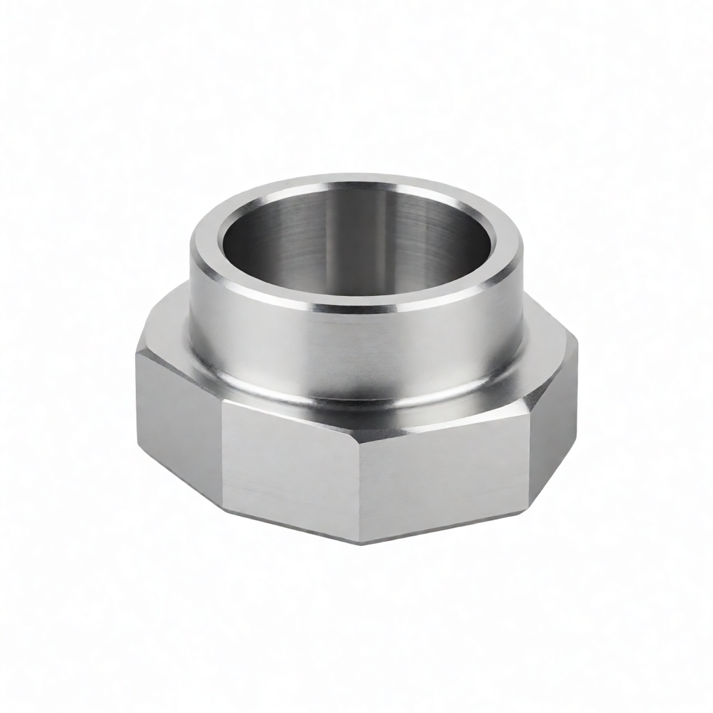
Aluminum CNC Machining: A Practical Guide to Tolerance Control
Aluminum CNC machining is a core aspect of precision manufacturing, yet achieving a ±0.01 mm tolerance is often constrained by tool wear, thermal deformation, and the release of clamping stress. Based on mass-production experience across 72 CNC machines, this guide systematically analyzes root causes and mitigation strategies for tolerance deviations in aluminum parts from three dimensions: material selection, process parameters, and inspection methods. The target audience comprises R&D engineers and technical procurement leads, with content focused on verifiable process logic rather than marketing rhetoric.
Material Baselines and Selection Logic for Aluminum CNC Machining
Material grade directly determines the width of the machining window. 6061-T6 and 7075-T6 are the most commonly used CNC aluminum alloys, but they exhibit significant differences in deformation behavior under cutting forces. 6061-T6 has a yield strength of approximately 270 MPa and better ductility, making it suitable for complex contour milling; 7075-T6 has a high yield strength of 500 MPa and greater stiffness but lower toughness, prone to micro-chatter marks during high-speed cutting. If a part requires both high stiffness and cosmetic finish, it is recommended to prioritize 7075-T6 while reducing spindle speed to 8000–10000 RPM to avoid stress concentration at the tool nose that can cause edge chipping.
For thin-walled parts (wall thickness <0.8 mm), material springback is the primary factor in tolerance loss. When milling thin-walled 6061, improper clamping force can cause dimensional shifts of 0.02–0.05 mm after stress relief. Engineering practice shows that changing the clamping method from “full-perimeter clamping” to “three-point floating support” can control springback errors in thin-walled parts to within 0.01 mm. During material selection, attention must also be paid to the pre-strain condition of the sheet or bar stock; T5 temper offers greater machining stability than T6, but suppliers must provide heat treatment certificates to avoid batch consistency issues caused by incoming material hardness variations.
Tolerance Budgeting and DFA Analysis for Aluminum CNC Machining
Tolerance control is not the responsibility of a single operation but a system engineering task across the entire process chain. A complete tolerance budget for aluminum CNC machining must break down sources of dimensional error: machine geometric error, tool wear, thermal deformation, and measurement uncertainty. Using a target tolerance of ±0.01 mm as an example, if measurement uncertainty is ±0.002 mm (based on CMM repeatability), the actual machining tolerance band must be controlled to within ±0.008 mm.
Introducing DFA (Design for Tolerance/Analysis) at the design stage is critical. If drawings specify multiple relative position dimensions (e.g., hole patterns), accumulated dimensional chain errors must be evaluated. For instance, with a double-hole location spanning 50 mm, if the single-location tolerance is ±0.02 mm, the worst-case accumulated error could reach ±0.04 mm. In such cases, R&D should be advised to modify the hole distance datum or add a common datum surface. Our DFM review stage outputs a tolerance feasibility report, identifying which dimensions are difficult to achieve stably in conventional CNC milling and require grinding or finish turning intervention.
Impact of Tooling Systems and Cutting Parameters on Precision
Tooling is the direct executor of tolerance control. In aluminum CNC machining, tool wear rates are typically higher than for steel, because aluminum is highly adhesive and has low hardness, leading to Built-up Edge (BUE/BUE formation). BUE alters the actual tool radius, causing undersized parts and degraded surface roughness. It is recommended to use TiN-coated or Teflon-coated aluminum-specific end mills, limiting tool usage per insert to no more than 3 hours and enforcing tool changes to avoid cumulative wear. Rough milling and finish milling must use separate tools; the finish mill diameter tolerance must be controlled to T1–T2 grade, and new tools require trial cuts to calibrate tool offset.
Regarding cutting parameters, for finish milling of aluminum, the depth of cut (Ap) is recommended at 0.2–0.5 mm, and the width of cut (Ae) at 40–60% of the tool diameter, with spindle speed maintained at 8000–12000 RPM (depending on tool diameter). The key principle is that “large depth of cut, small width of cut” tends to cause tool vibration, thereby amplifying form and position errors; “small depth of cut, large width of cut” is favorable for heat dissipation and surface quality. For mirror finish requirements (Ra<0.4 μm), the finish milling feed rate must be reduced to 0.02–0.03 mm/Tooth, using a climb milling strategy to smooth surface transitions by leveraging the tool engagement angle.
Practical Essentials of Clamping Deformation and Thermal Compensation
Clamping stress is a silent killer. In aluminum CNC machining, if the part has low rigidity, local deformation caused by vacuum suction or mechanical clamping can rebound by more than 0.03 mm after release. Solutions include adding spring pad buffers when designing dedicated fixtures; for thin sheet parts, using double-sided adhesive film clamping; or using hydraulic plates for uniform pressure application. Additionally, temperature compensation must not be ignored. At a shop floor room temperature of 25°C, aluminum’s coefficient of thermal expansion is 23 μm/m·°C; if the machine tool experiences thermal drift of 0.5°C, thermal deformation of a 100 mm long workpiece can reach 1.15 μm. Precision parts must be machined in a thermally controlled room (20±1°C), and the workpiece must be stabilized for 15 minutes after clamping before machining to achieve thermal equilibrium.
For high-precision hole systems, thermal compensation must also account for tool holder extension. Thermal expansion of the tool holder during high-speed cutting leads to Z-axis overcut. Use the thermal compensation formula L=α×L0×ΔT for estimation, or directly correct the G43 value on the machine through boring tests. We require a first-hole trial cut and diameter measurement for each batch before machining critical holes, with data entered into the MES system as the basis for subsequent compensation.
Comparison of Aluminum CNC Machining Solutions and Inspection Methods
Different machining processes involve trade-offs between tolerance control capability and cost. The table below compares three common aluminum machining paths—milling, turning, and Swiss-type turning—in terms of performance under a ±0.01 mm tolerance, for procurement selection reference.
| Process Type | Applicable Geometric Features | ;Typical Tolerance Range | Surface Roughness Ra | Key Risk Points |
|---|---|---|---|---|
| 3-axis/5-axis Milling | Complex free-form surfaces, non-standard housings, thin-walled parts | ±0.01-0.02mm | Ra0.4-0.8μm | Tool tip wear accumulation, thermal deformation, clamping stress |
| CNC Turning | Parts of revolution, shafts, flanges | ±0.01-0.01mm | Ra0.2-0.4μm | Tailstock center runout, tool deflection, thermal growth |
| Swiss-type Turning | Long slender shafts, miniature connectors, medical devices | ±0.003-0.008mm | Ra0.2μm | Guide plate wear, micro-vibration, built-up edge (BUE) in grooving |
For inspection methods, Coordinate Measuring Machines (CMM) serve as the definitive arbitration tool, suitable for first-article inspection and sampling; optical imaging measurement systems offer high efficiency for rapid screening of planar features and hole positions; roughness testers must be calibrated synchronously with standard reference blocks. For batch orders, it is recommended to execute a full-dimension GO/NO-GO pre-check prior to shipment, maintain a CMM sampling ratio of at least 10%, and perform 100% inspection of critical features. All data must retain the original CSV files to ensure traceability.
Common Failure Modes and Batch Consistency Control
In mass production, tolerance drift is often caused by "slow variables". End-of-tool-life, thinning of the lubricant film on machine guideways, and seasonal temperature changes all lead to positive dimensional drift. The countermeasure is to establish a tool life warning system: trigger tool changes based on total cutting meters rather than time; execute a standard bar thermal equilibration program at daily startup; and perform laser interferometer verification monthly. Regarding appearance, high-lustre finishes require the absence of scratches, necessitating manual polishing or chemical polishing processes after machining; however, polishing sacrifices some dimensional accuracy, so allowances must be reserved in the DFM (Design for Manufacturing).
We emphasize "in-process patrol inspection" rather than relying solely on final inspection. Sample critical dimensions every 2 hours; if the SPC control chart shows a trend of 5 consecutive points on the same side, immediately stop the line for investigation. Batch consistency is derived from a machine capability index Cmk≥1.33; if a process Cmk is insufficient, equipment must be upgraded or drawing tolerance requirements relaxed. This also forms the basis for aligning quality expectations with customers: not all ±0.01mm tolerances can be achieved stably at low cost; specific geometric features must be evaluated.
What is the minimum tolerance for CNC machining of aluminum alloys?
Standard 3-axis milling can stably achieve ±0.01mm, while Swiss-type turning or precision turning can remain stably within ±0.01mm. Smaller tolerances rely on grinding or dedicated fixture compensation, resulting in exponential cost increases. ±0.003mm falls into the ultra-precision category and is not a standard CNC process.
How to avoid thermal deformation in CNC machining of aluminum alloys?
Control the workshop at a constant 20±1℃, allow the workpiece to rest for 15 minutes after clamping, apply thermal compensation values to tools, and maintain an interval of more than 30 minutes between rough and finish milling to allow sufficient heat dissipation. Thin-walled parts are particularly sensitive and require clamping with floating supports.
How to achieve a surface roughness of Ra0.4μm in CNC machining of aluminum alloys?
Finish milling should use a climb milling strategy, with a depth of cut ≤0.3mm, a feed rate of 0.02-0.03mm/Tooth, and highly sharp tool edges without chipping. If a mirror finish is required (Ra<0.2μm), electro-polishing or precision honing must be added after machining.
How to ensure consistency in batch CNC machining of aluminum alloys?
Rely on SPC process monitoring, perform CMM full inspection of first and last articles of each batch, enforce tool changes based on cutting meters, and use Cmk≥1.33 as the release threshold. 72 machines utilize a MES system to unify process parameters and compensation values, avoiding human variability.
What is required for custom CNC machining of aluminum alloys from drawings?
Provide 3D STEP/IGES models, 2D drawings with annotated tolerances and roughness, material grades (e.g., 6061-T6), and surface treatment requirements (e.g., anodizing film thickness). If mating parts are involved, it is recommended to provide mating gap specifications to facilitate DFM optimization and datum selection.
Tolerance control is a system engineering discipline, not a single-point optimization. If your project involves the batch delivery of aluminum parts with critical functional dimensions, we recommend sending your drawings and tolerance requirements to us. Our engineering team will provide a DFM audit report and process route recommendation within 48 hours, helping to lock in a feasible tolerance budget and cost structure.