





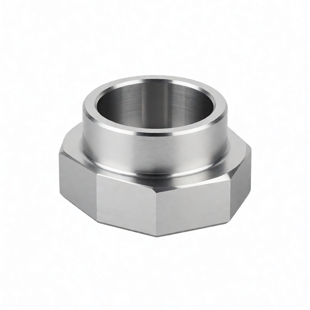
The Core Value and Engineering Logic of Aluminum Alloy Turning-Milling Composite Machining
Turning-milling composite machining is a processing method that completes multiple operations—such as turning, milling, and drilling—in a single setup on a single CNC machine tool, utilizing multi-axis linkage and simultaneous axial/radial tool movements. For aluminum alloy, a material characterized by high thermal conductivity, good machinability, and susceptibility to deformation, traditional sequential processes (e.g., "turn first, then mill") or multiple setups often lead to accumulated clamping errors and unstable surface finish. The core value of aluminum alloy turning-milling composite machining lies in minimizing workpiece movements, leveraging the machine tool's high-rigidity spindle and rapid tool change systems to achieve surface roughness of Ra0.4μm or lower within a tolerance range of ±0.01mm. This process is particularly suitable for parts requiring both precision internal/external bores and complex contours or end faces, such as aerospace fasteners, precision supports for semiconductor equipment, and high-performance heat sinks. For procurement and engineers, the key to determining whether to adopt this process lies in evaluating the part's geometric complexity, material lot consistency, and final cosmetic quality requirements.Applicable Scenarios: When to Choose Turning-Milling Composite over Sequential Machining
Not all aluminum alloy parts are suitable for turning-milling composite machining. The decision primarily relies on the part's degrees of freedom and clamping risks.High Coaxiality and Polyhedral Parts
When a part design requires coaxiality between the internal bore and external diameter exceeding 0.005mm, and both end faces require milling or boring, sequential machining easily results in coaxiality deviation due to secondary positioning. Turning-milling composite machining ensures dimensional correlation across all features in a single setup.Thin-Wall and Deformation-Prone Structures
Aluminum alloys (such as 6061-T6 or 7075-T6) are prone to elastic deformation under cutting heat and fixture stress. In traditional workflows, each time the fixture is released, the springback causes dimensional out-of-tolerance. Turning-milling composite machining, by optimizing the tool path and depth of cut combined with the machine tool's high-precision feedback, can control deformation to the micrometer level.Integrated Functional Components
If a part integrates heat dissipation fins, sealing grooves, locating steps, and threads, distributed machining not only increases the number of operations but also raises the risk of surface scratches. Turning-milling composite machining completes all features in a single workflow, significantly enhancing cosmetic consistency.Material Grade and Cutting Parameter Matching Guide
The machinability of aluminum alloys varies significantly; selecting the correct grade is a prerequisite for ensuring the efficiency of turning-milling composite machining.| Material Grade | Typical Hardness (HB) | Cutting Speed (Vc, m/min) | Turning-Milling Composite Advantageous Scenarios | Primary Failure Risks |
|---|---|---|---|---|
| 6061-T6 | 95 | 300-600 | General structural parts, heat sinks | Built-up edge (BUE), surface burrs |
| 7075-T6 | 150 | 150-300 | High-strength load-bearing structures, aerospace parts | Rapid tool wear, requires high rigidity |
| 5052 | 40-60 | 200-400 | Thin-wall containers, appearance parts | Susceptible to scratches, sensitive to fixture contact surfaces |
For the 6061 series, it is recommended to use TiAlN or CVD diamond-coated tools to reduce the coefficient of friction. Since 7075 has high strength and generates large cutting forces, attention must be paid to spindle load during turning-milling composite machining to avoid high-frequency vibrations that affect surface finish. Although 5052 is soft, it is highly sensitive to clamping marks; soft jaws must be used for protection, and finishing operations should be performed at the end of the milling sequence.
Process Path Optimization: From Rough Machining to Mirror Finishing
The machining strategy for aluminum alloy turning-milling composite machining directly determines the final quality. A "uniform stock allowance" strategy is recommended.Rough Machining Stage
Adopt large depth of cut (1-3mm) and high feed rates to rapidly remove excess material. Surface quality need not be a priority at this stage; the focus is on stress removal. For complex contours, 4-axis or 5-axis linkage can prevent tool interference and optimize tool paths.Semi-Finishing and Finishing
Leave a stock allowance of 0.1-0.2mm for semi-finishing smoothing. During finishing, reduce cutting speed and increase feed rate, with the goal of controlling the Ra value to within 0.4μm. For high-gloss requirements, a light finishing milling pass can be added after finishing turning, using the milling tool's periphery to correct the helical marks left by turning.Surface Quality Control
Aluminum alloy surfaces are extremely susceptible to scratches and color variation. The advantage of turning-milling composite machining is that it does not require flipping the part, avoiding secondary contamination and chipping caused by manual loading/unloading. By controlling tool retraction paths via program, surface dwell time can be minimized to ensure batch consistency.Inspection Standards and Key Acceptance Points
High-quality turning-milling composite parts must Undergone through a rigorous inspection process.- Dimensional Accuracy: Critical dimensions are spot-checked using a Coordinate Measuring Machine (CMM) to ensure tolerances are maintained within ±0.01mm. For parts with a high length-to-diameter ratio, the effectiveness of thermal deformation compensation must be monitored closely.
- Surface Roughness: Ra values are measured using an optical profilometer. For mirror-like finishes (e.g., audio enclosures), Ra must be below 0.2μm, and checks for microscopic chatter marks are required.
- GD&T: Focus is placed on inspecting concentricity, perpendicularity, and flatness. The advantage of turning-milling composite machining is that these metrics are typically superior to step-by-step machining; however, verification is needed to ensure the fixture system remains sufficiently rigid relative to the tooling.
- Visual Inspection: Parts are visually inspected under standard light sources to confirm the absence of scratches, oxidation spots, and tool marks. This is a key differentiator between generic CNC shops and high-quality custom manufacturers.


