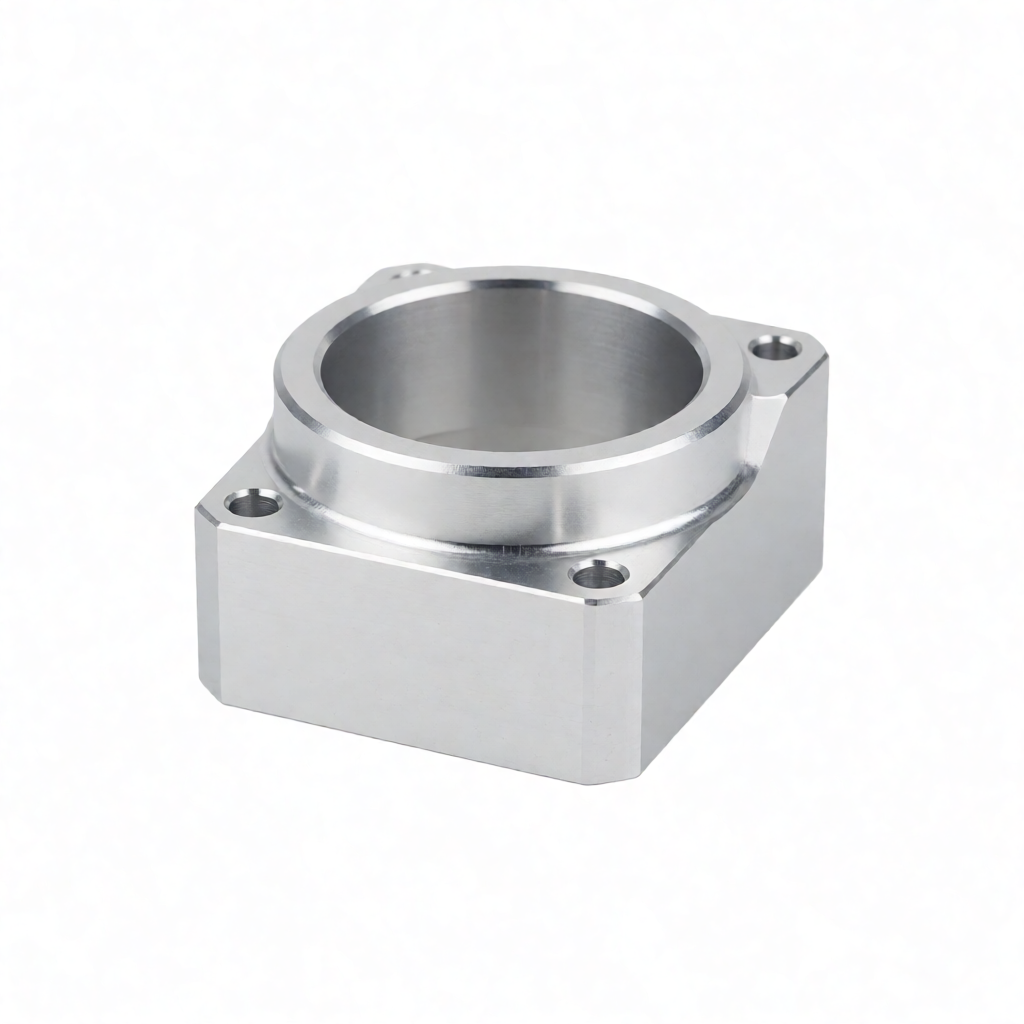
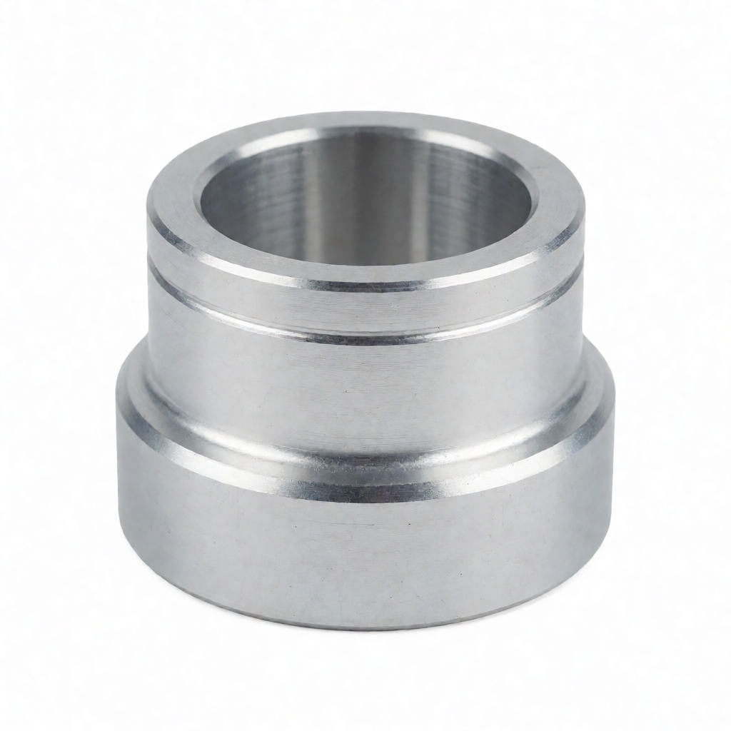
Analysis of Deformation Causes and Process Challenges in CNC Machining of Aluminum Alloy Thin-Walled Parts
Aluminum alloy thin-walled parts are highly susceptible to deformation in precision CNC milling due to the accumulation of cutting heat, the release of fixture stress, and the reorganization of residual material stresses. Aluminum profiles or plates with wall thicknesses less than 2mm lack sufficient rigidity during milling; when subjected to radial cutting forces from the tool, they are prone to elastic vibration, which can lead to dimensional deviations and degraded surface roughness. The core objective of the key topic "preventing deformation in aluminum alloy thin-walled part machining" lies in balancing the thermal expansion coefficient (approximately 23.5×10⁻⁶/°C for 6061-T6) with cutting forces.
For technical procurement specialists and engineers, understanding failure modes is a prerequisite for material selection and process planning. Common deformation patterns include bulging in clamped areas, warping in unclamped areas, and coaxiality deviations in threaded holes. These phenomena are often not caused by a single factor, but rather by the combined effect of fixture design, tool paths, cooling strategies, and material pretreatment. If residual stress release is overlooked, consistency in batch production will be difficult to guarantee even if tolerances are set reasonably, leading to higher rework rates and delivery delays.
Engineering Selection Strategies for Material Pretreatment and Fixture Design
Effective deformation prevention begins at the material level. Using 6061-T651 or 7075-T7351 aluminum alloy bars or plate materials that have undergone stress-relief annealing can significantly reduce stress drift during machining. The T51 temper condition offers a higher internal stress release capacity than the T6 condition, making it particularly suitable for complex thin-walled structural components. Additionally, material thickness tolerances must be controlled within ±0.05mm to avoid sudden changes in local cutting forces caused by uneven blanks.
Fixture design must adhere to the "minimum deformation" principle. Vacuum suction fixtures are suitable for flat, thin components, as they distribute suction force evenly through air pressure, avoiding indentations caused by localized point pressure. For irregular shapes, it is recommended to use soft jaws combined with V-blocks; the contact surfaces should be lined with rubber or polyurethane padding to protect the surface. Avoid excessive clamping force; in general, the preload should be kept within 10% of the part's yield strength. If the part has a deep cavity structure, it is advisable to add internal support pillars within the cavity to prevent the side walls from bending toward the empty space during cutting.
Empirical Comparison of Tool Path Optimization and Cutting Parameters
Tool paths critically affect the rigidity of thin-walled parts. In traditional one-way milling, the tool suddenly loses contact when changing tools, causing the thin wall to bounce back instantly. Adopting a "semi-finishing with stock allowance" strategy involves completing the majority of the cutting at a lower feed rate, leaving a finishing allowance of 0.2-0.5mm, and finally performing light finishing milling. The Z-axis stepping strategy should remain constant to avoid pneumatic shocks caused by frequent tool changes.
The following table compares the performance of three typical milling strategies on 6061 aluminum alloy parts with a wall thickness of 1.5mm:
| Strategy Type | Spindle Speed (rpm) | Feed Rate (mm/min) | Surface Roughness Ra (μm) | Dimensional Deviation (mm) | Application Scenario |
|---|---|---|---|---|---|
| Heavy Cutting (Single Pass) | 8000 | 2400 | 1.6-2.0 | ±0.03-0.05 | Prototype verification, non-aesthetic surfaces |
| Layered Shallow Cutting + Polishing | 12000 | 1800 | 0.8-1.2 | ±0.01-0.02 | General structural parts, medium batch sizes |
| Micro-milling | 24000 | 1500 | 0.4-0.6 | ±0.005-0.01 | High-precision aesthetic parts, critical mating surfaces |
The micro-milling strategy requires the use of small-diameter end mills (such as D2-D3) paired with high-speed electric spindles. Under these conditions, cutting forces are extremely low, minimizing part deformation. However, note that small tool diameters have low bending stiffness; short-shank holders (such as SHANK 6mm) must be used to prevent chatter. For batch production, layered shallow cutting achieves a better balance between efficiency and accuracy, and is recommended as the standard process.
Coolant Systems and Real-Time Control of Thermal Deformation
Cutting heat is another major cause of thin-walled part deformation. It is recommended to use fully enclosed pressure cooling or spray cooling to avoid thermal shock deformation caused by coolant directly impacting finished thin-walled surfaces. Coolant temperature should be controlled at 20±5°C. If using a constant-temperature water …, keeping the thermal deformation source within 0.005mm.
Real-time monitoring of tool wear status is also critical. When the tool edge radius (wear land VB) exceeds 0.2mm, cutting resistance increases significantly, easily inducing micro-vibrations in the workpiece. It is recommended to set tool life compensation in the CAM software, or use an online probe to detect tool length and radius compensation values before machining critical features. For long-term mass production, periodically calibrating the spindle thermal drift curve and correcting tool offsets can effectively compensate for thermal errors.
Inspection Methods and Batch Consistency Control Strategies
A key challenge in inspecting thin-walled parts is fixture-induced deformation. When using a Coordinate Measuring Machine (CMM), soft probing forces must be employed; recommended probe force values are 0.5–1.0N to prevent thin-wall compression that distorts data. For critical hole positions and mating surfaces, it is recommended to use optical projectors or structured light scanning systems to achieve non-contact 100% inspection, thereby eliminating interference from contact stress.
Regarding batch consistency control, establish a “First Article Inspection (FAI) + Periodic Patrol Inspection” mechanism. The first article must undergo full dimensional inspection and surface roughness measurement; mass production may only commence after it passes. For every 50 parts produced or upon tool change, critical dimensions must be sampled for inspection. Additionally, record the material heat number, cutting parameters, and coolant concentration for each batch to establish a process traceability archive. If a dimensional drift trend is detected, immediately stop the machine to analyze whether it is caused by cumulative tool wear or spindle thermal deformation, rather than blindly adjusting tolerances.
Frequently Asked Questions (FAQ)
How can internal stresses be effectively relieved in machined aluminum thin-walled parts?
Low-temperature aging (holding at 150–170°C for 2–4 hours) can be used to release residual stress, or stress-relief annealing can be performed on the blank prior to machining. For precision parts, low-temperature aging is recommended after finishing to stabilize dimensions.
Is micro-machining suitable for all aluminum alloys?
Not entirely. Soft aluminum grades like 6061 and 6082 are suitable for micro-machining. For high-strength aluminum alloys like 7075, which have higher hardness, a layered shallow-cutting strategy is recommended, with an appropriate increase in feed rate to avoid the “plowing” effect.
How to balance machining efficiency with deformation prevention for thin-walled parts?
By rationally distributing the machining allowance, keep the finishing allowance within 0.2mm, increase the finishing feed rate, and reduce the depth of cut. Utilize the “Adaptive Milling” function in CAM software to optimize tool path length, improving efficiency while maintaining rigidity.
What specific failure modes can result from improper fixture design?
Local dents, deformation in the clamping area, and warpout in unclamped areas. These manifest as dimensional out-of-tolerance, surface scratches, and coaxiality deviations in hole positions. These can be mitigated by adding backing pads, adjusting clamping point locations, or switching to vacuum suction clamping.
How to monitor thermal deformation trends in mass production?
Record spindle temperature and coolant temperature curves and compare dimensional changes between the first article and subsequent parts. If deviations show a linear increase, it is likely thermal drift; if they fluctuate randomly, it is likely tool wear or loose clamping. It is recommended to use the data from the first 30 minutes of each batch to calibrate tool offsets.
Conclusion and Recommendations
Deformation prevention in aluminum thin-walled parts is a comprehensive engineering challenge involving material, fixtures, tooling, cooling, and inspection systems. There is no single “magic parameter”; only systematic optimization of the process chain is effective. For purchasers, selecting a manufacturer with complete inspection capabilities (CMM, optical scanning) and a process traceability system is more critical than simply pursuing the lowest price.
If you have drawings for thin-walled aluminum parts and need to evaluate process feasibility or obtain detailed quotations, please send your CAD data via email for technical assessment. We can provide DFM advice, material selection guidance, and batch consistency control solutions to help you shorten R&D cycles and reduce mass production risks.