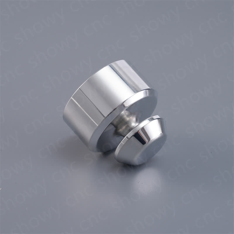


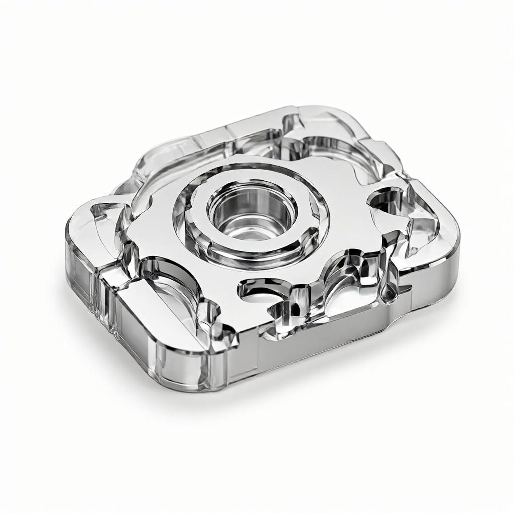
Encoder parts take on the task of position and velocity feedback in precision automation systems. Glass and ceramic materials become key materials for high-end applications due to their high hardness, low thermal expansion coefficient and excellent electrical insulation.
Analysis of Core Precision Index of Glass and Ceramic Encoder
The accuracy of encoder parts directly determines the system response speed and positioning reliability. For glass and ceramic materials, key indicators include geometric tolerance, surface roughness and thermal stability. Typical application scenarios require flatness control within ±0.005mm, roundness error ≤0.01mm, surface roughness Ra ≤0.2μm. The Mohs hardness of glass (such as borosilicate glass) is about 5.5-6, and the Mohs hardness of ceramics (such as alumina) reaches 9. Both of them far exceed the processing limits of conventional metal tools and require special processing techniques.
Geometric tolerances and functional associations
Geometric deviation of encoder disc or rotor will be directly converted into measurement error. For example, the roundness exceeding 0.01mm may introduce an angle error of about 0.0056° in 1024-line encoder, which has a significant impact on high-precision servo systems. The low thermal expansion coefficients of glass and ceramics (glass about 3.3×10/°C, alumina about 8.1×10/°C) make their size stability better than metals in high temperature environments, but the thermal management of the processing process still needs to be strictly controlled.
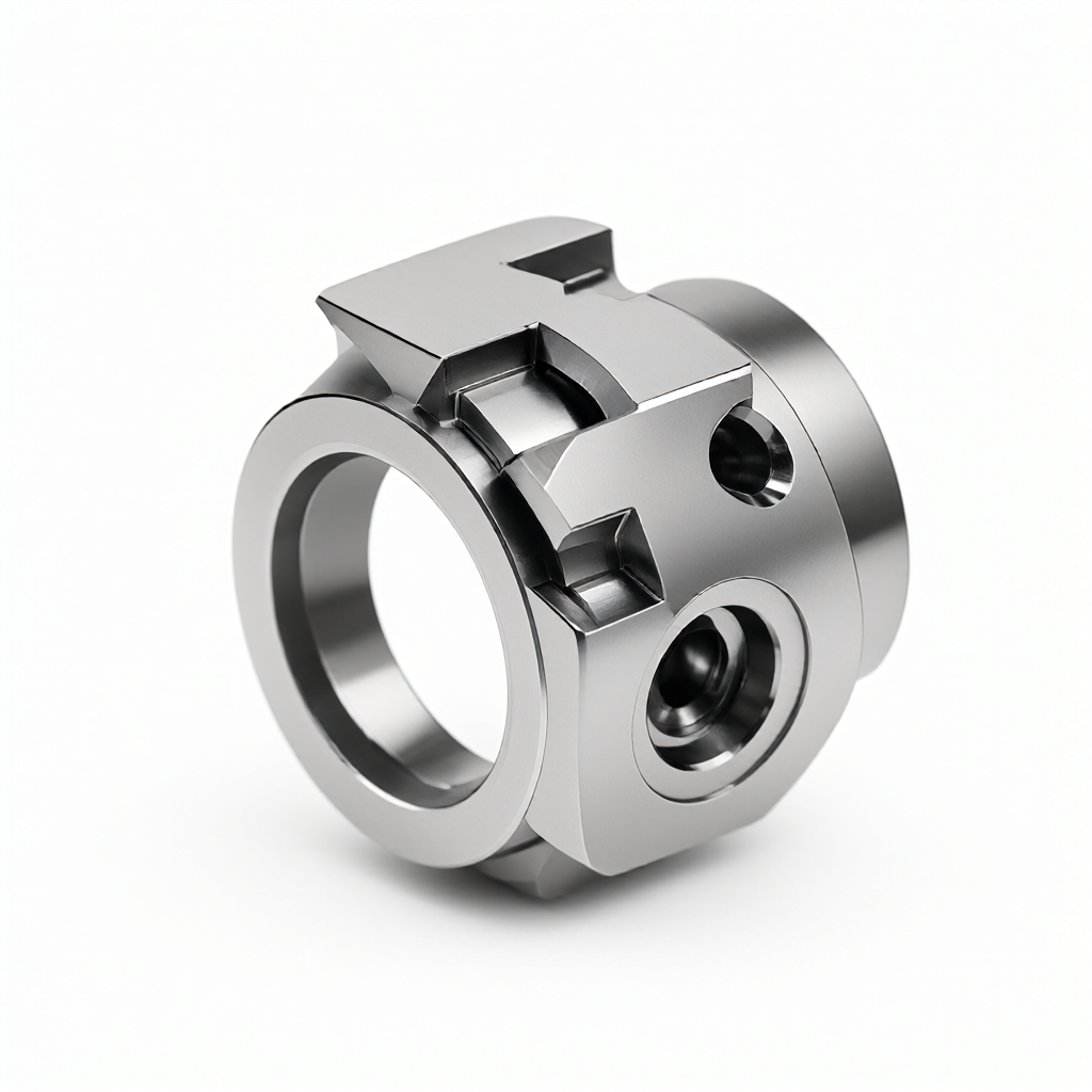
Difficulties and Failure Modes in Glass Ceramics Processing
The brittle fracture characteristics of glass and ceramics make their processing unique challenges. The main difficulties include:
- microcrack risk: Improper grinding parameters lead to sub-surface cracks, reducing part fatigue life
- Low material removal rate: traditional cutting efficiency is insufficient, need to use ultra-precision grinding or laser processing
- form tolerance retention: Thin-walled glass parts are easily deformed under clamping stress and their size drifts after unloading
- surface damagePlastic deformation layer produced by grinding affects optical performance of encoder
Failure mode analysis shows that 70% of glass encoder machining defects are due to improper clamping or insufficient optimization of grinding parameters. For example, when thin-walled glass rotors are clamped with V-blocks, local stress concentration may lead to cracks within 24 hours after machining. Avoidance solutions require special tooling design combined with material characteristics and progressive clamping strategy.
Process comparison: ultra-precision grinding vs laser machining
For glass and ceramic encoder parts, the mainstream processes include ultra-precision grinding and laser machining, both of which have advantages and disadvantages in accuracy, efficiency and surface quality:
| Compare Dimensions | ultra-precision grinding | laser processing |
|---|---|---|
| size tolerance | ±0.005mm | ±0.01mm |
| surface roughness | Ra 0.1-0.2μm | Ra 0.3-0.5μm |
| material removal rate | 0.5-2mm³/min | 1-5mm³/min |
| HAZ (heat affected zone) | almost no | Yes, power control required |
| Applicable materials | Glass, ceramic, hard alloy | Glass, some ceramics |
| batch consistency | tall | medium |
| cost effectiveness | High (batch size ≥ 100 pieces) | Medium (small batch flexible) |
Ultra-precision grinding is suitable for optical encoders where surface quality is critical and requires the use of diamond wheels with in-line monitoring; laser machining is advantageous for small batch prototypes or complex features, but thermal management needs to be carefully controlled to avoid micro-cracks. For mass production, the stability of the grinding process is preferred by buyers as it can be used with automatic loading and unloading for continuous machining.
Control of critical process parameters
Wheel selection, feed rate and cooling strategy are critical in grinding. Resin bonded CBN wheels with a grain size of 400 - 600 and a linear speed of 30 - 50 m/s are recommended for glass processing, while electroplated diamond wheels with a linear speed of 20 - 30 m/s are recommended for alumina ceramics. The coolant temperature is controlled at 25 ± 2 ° C to avoid thermal shock. dure laser proces, that pulse energy is 200 - 500 mJ, and the repetition frequency is 1 - 5 kHz, which needs to be dynamically adjusted according to the absorption rate of the material.
Key points of clamping and tooling design
The brittleness of glass and ceramics places special demands on the clamping scheme. It is recommended to use air expansion clamping jaws or vacuum suction cups to avoid local stress concentration. Thin wall parts (wall thickness<1mm)需使用定制衬套工装,配合三点定位原则减少变形。装夹力应控制在 0.5-1N/cm² 范围内,并通过有限元分析预测应力分布。对于直径 >50 mm glass code disc, it is recommended that the preloading treatment before grinding, eliminate the residual stress.
Selection of tooling materials
The tooling itself shall have low thermal expansion coefficient. Invar or ceramic tooling is recommended to avoid dimensional drift due to temperature change during processing. The surface roughness of tooling shall be Ra ≤ 0.1 μ m to prevent scratching of workpieces. During batch production, tooling life management shall be included in process control, and dimensional calibration shall be conducted once every 500 pieces.
Test Method and Acceptance Criteria
Glass and ceramic encoder parts are inspected in three dimensions: dimension, geometric tolerance and surface quality. Key inspection items include:
- physical dimension: Use a coordinate measurement machine (CMM) to measure the critical diameter and thickness with an accuracy of ± 0.002mm
- form and location toleranceRoundness and flatness are measured by laser interferometer or autocollimator, resolution 0.001mm
- surface finish: Ra value measured by roughness meter, microcrack examined by optical microscope (magnification 50- 100X)
- thermal stability: Simulate operating temperature cycling (-40 ° C to 85°C), detect size change rate
The acceptance criteria shall specify the AQL level. It is suggested that the key size shall be fully inspected, and the surface defects shall be sampled according to AQL 0.65. For optical encoders, the transmittance and reflectance shall be additionally tested to ensure compliance with design specifications. The test data shall be fully recorded to support batch traceability.
Batch Consistency Assurance Strategy
The mass production of glass and ceramic encoder parts requires the establishment of a full-process control system. Key measures include:
- incoming inspection: Raw material batch consistency verification, checking glass composition or ceramic sintering density
- process monitoring: On-line measurement of critical size, SPC control chart monitoring of grinding process stability
- fixture management: Regularly calibrate tooling size, establish wear model to predict replacement cycle
- environmental control: Constant temperature and humidity workshop (20±1°C, RH 50±5%), reduce thermal deformation
Through the combination of first article confirmation and batch sampling inspection, the batch size fluctuation can be controlled within ±0.005mm. The purchaser shall specify tolerance requirements and inspection standards when inquiring, so as to facilitate the supplier to formulate corresponding process route and quality control scheme.
frequently asked questions
Glass encoder parts after processing surface micro-cracks how to do?
Microcracks are usually caused by improper grinding parameters or clamping stresses. It is recommended to optimize the grinding wheel grain size (increase to 600-800), reduce the feed speed by 20%, and adopt a progressive clamping strategy. Also check the coolant flow to ensure adequate heat dissipation.
How to control thermal deformation in ceramic code plate processing?
Alumina ceramics have a high coefficient of thermal expansion, so cutting heat needs to be controlled during processing. It is recommended to use low-temperature coolant (10-15°C) to reduce the grinding speed by 30%, and leave it for 24 hours after processing to stabilize the size before testing.
How long is the lead time for a prototype of a small batch glass encoder?
Depending on structural complexity and surface requirements. Simple flat glass parts can be delivered in 7-10 days and complex curved parts in 15-20 days. It is recommended to provide complete drawings and tolerance requirements for rapid evaluation of the process route.
How to ensure size consistency in mass production?
SPC process control is adopted, key size is sampled and measured every 50 pieces, CPK ≥1.33 is regarded as process stability. Tooling is calibrated once every 500 pieces to ensure that positioning accuracy does not drift. Environmental constant temperature control is also a key factor.
Is there a big difference in processing costs between glass and ceramic encoders?
Ceramic materials usually cost 30-50% more than glass, and are harder to process (harder), so the overall cost may be 50-100% higher. However, ceramics have better thermal stability and wear resistance, and longer long-term service life. The specific cost depends on the size, tolerance and batch evaluation.
Conclusions and recommendations for action
The precision machining of glass and ceramic encoder parts requires comprehensive consideration of material characteristics, process selection and inspection standards. Ultra-precision grinding is suitable for high-precision mass production, and laser machining is flexible for small-batch complex parts. The purchaser should provide complete drawings, tolerance requirements, material grades and batch information at the time of inquiry so that the supplier can optimize the process route and cost. If you have specific project requirements, please send drawings and technical requirements. We will provide one-stop solutions from DFM proposal to batch delivery based on 72 CNC equipment groups and professional inspection equipment.