

Robot Cable Connector: Precision Injection Molding and Airtightness Design Essentials
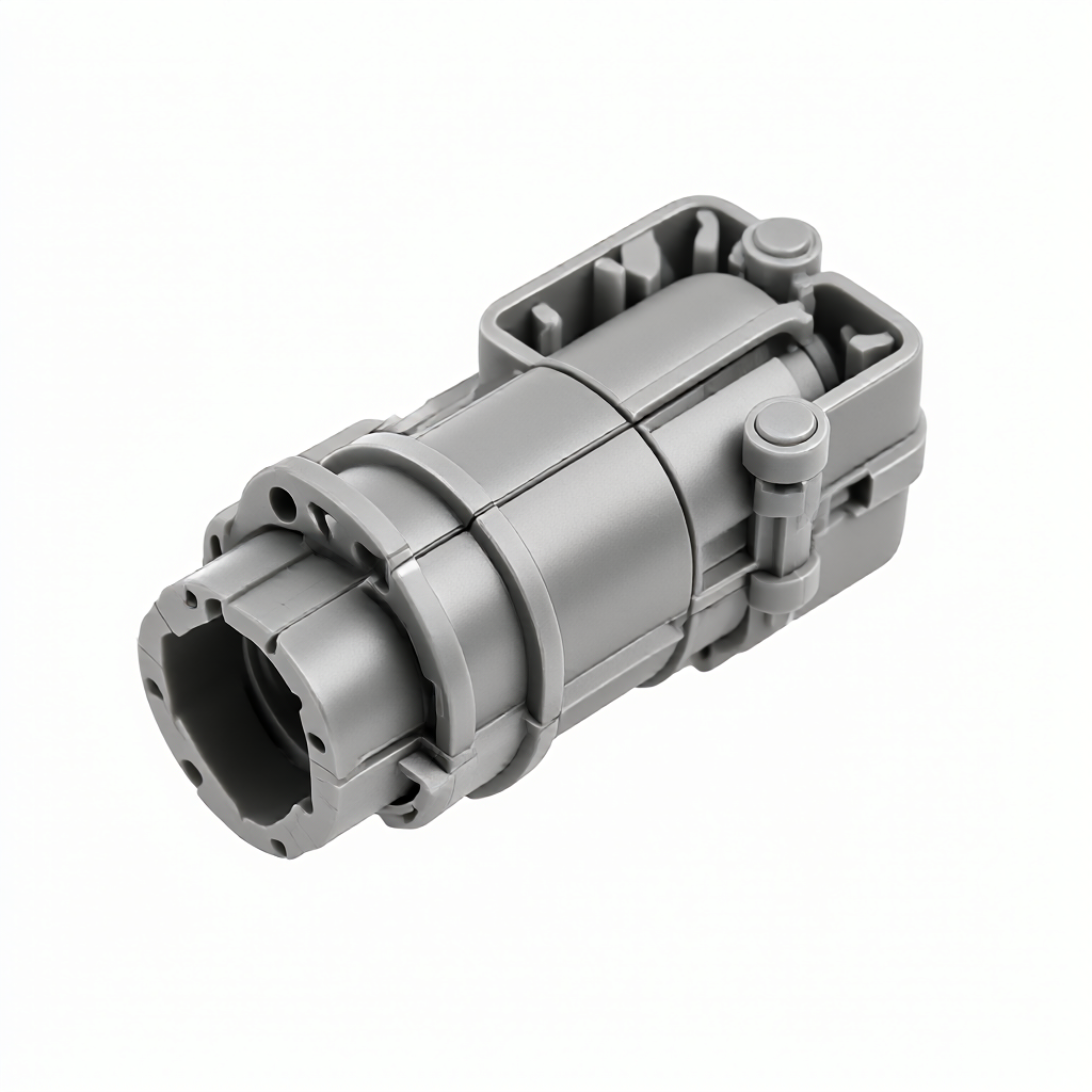
In collaborative robots, service robots and industrial automation joint modules, cable connectors (Connector & Housing) need to meet electrical signal transmission, mechanical locking, IP protection and long-term temperature cycle requirements. Many purchases are easy to fall into the "material selection" mistake, but ignoredStructural tolerances, welding process and air tightness testingThe impact on final assembly yield. For injection precision molding and air tightness control of robot cable connectors, the core lies in the combination of DFM (Design for Manufacturing) in the design stage and process parameters in the production stage to ensure that the size drift in mass production is less than ±0.02mm and IP67 or higher protection level is met.
Material selection: balance electrical properties and mechanical strength
The connector housing is usually injection molded from PA66, PBT or PC/ABS alloy, and the internal terminals are copper alloy. Material selection directly affects shrinkage and tolerance control. Recommended for applications with limited space in robot jointsPBT (polybutylene terephthalate), its glass transition temperature is higher, its size stability is better than PA66, and its warp deformation is smaller in temperature cycling tests from-40℃ to 125℃.
- PA66 GF30: High strength, but high water absorption, need drying treatment, suitable for non-strict airtight scenes.
- PBT GF30: Low moisture absorption, high rigidity, suitable for precision mating surface, air tightness is more stable.
- PC/ABS alloy: Good toughness, impact resistance, suitable for man-machine interaction interface that needs frequent plugging and unplugging.
Terminal materials commonly used C194 or C110 oxygen-free copper, tin or nickel plating surface. Coating thickness should be controlled in 0.5-2μm, too thick will increase contact resistance, too thin corrosion resistance is insufficient. For high frequency signal transmission, gold-plated terminals can provide a more stable low impedance connection.
Injection molding process: key parameters to control shrinkage and warpage
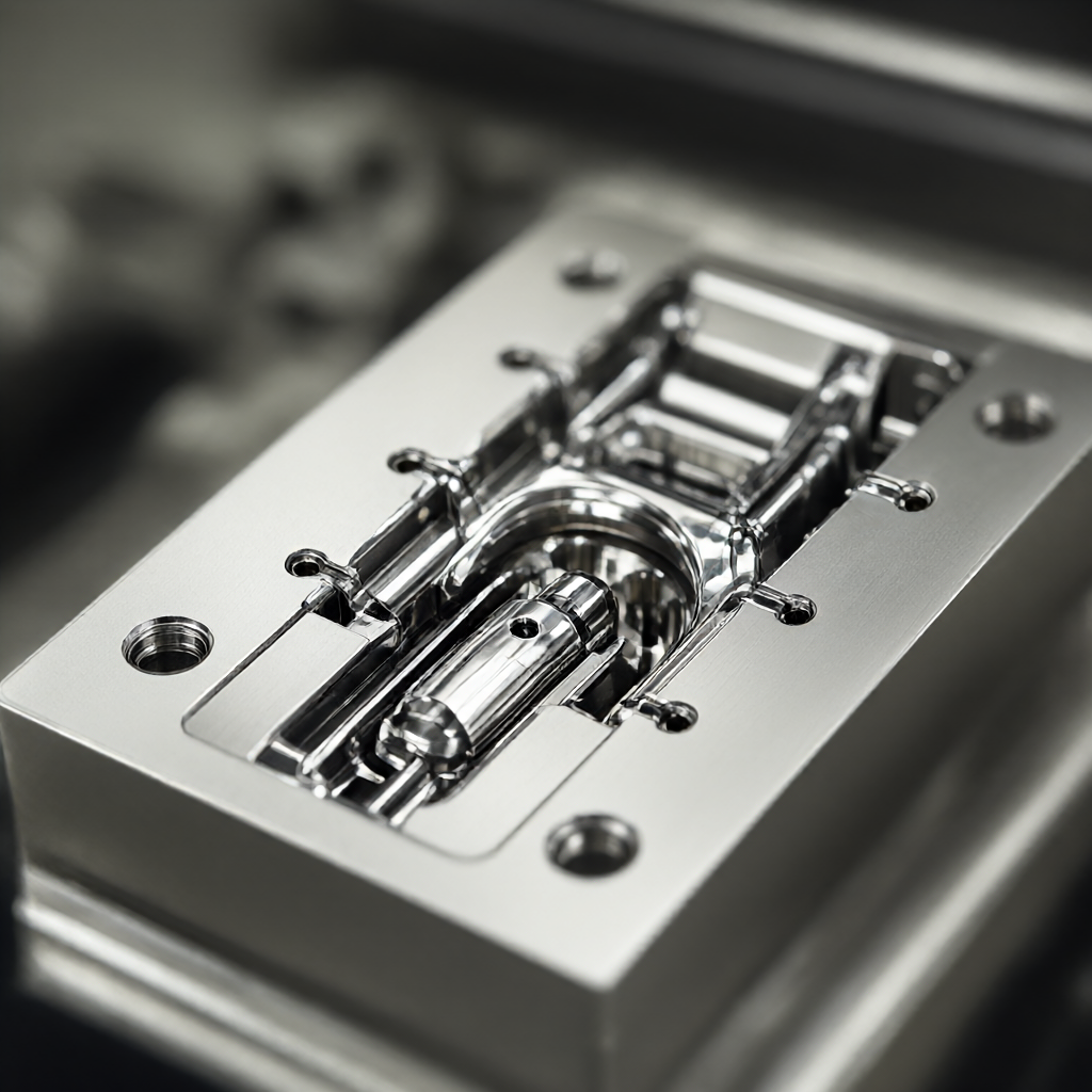
The tolerance of precision connectors is usually required to be within ±0.05mm, and the critical mating surface needs to reach ±0.02mm. This requires that the injection molding machine has a high response speed servo drive and a mold temperature machine. The mold design should adopthot runner systemTo avoid weight deviation and appearance defects caused by cold runner material head. Gate position should be far away from precision mating surface to reduce weld line and stress concentration.
| parameters/factors | general setting | Precision Recommended Settings | Effect on airtightness/size |
|---|---|---|---|
| mold temperature | 80-100℃ | 120-150℃(PBT/PA66) | Increasing mold temperature can reduce crystallinity difference and warp. |
| dwell time | 5-10 second | 10-15 Seconds (Phased) | Extend the pressure to compensate for shrinkage, but too long leads to residual internal stress |
| cooling time | 8-12 second | 12-18 Seconds (Symmetric Cooldown) | Fully cooled demoulding can reduce deformation, but it needs to balance production capacity |
| screw speed | high rotation speed | Low speed (<50%) | Reduce shear heat, avoid material degradation and bubbles |
Must be done before productionMoldflow analysis, simulate filling, cooling and warping, identify potential shrinkage and weld line position. For connectors with sealing grooves, special attention should be paid to the flatness of the sealing area, usually the flatness is ≤0.05mm, otherwise the O ring or silicone seal ring cannot be uniformly compressed, resulting in airtight failure.
Airtightness design: from IP rating to actual leakage rate
Robotic joint connectors often need to reach IP67 (short-term immersion) or even IP69 K (high-pressure high-temperature flushing). Airtightness depends not only on the housing material, but also onSeal Structure Design and Assembly Technology. Common scenarios include:
- O-ring + groove: Low cost, suitable for static sealing, but check whether the compression is maintained at 15-30% after plugging.
- Silicone bellows: Suitable for cable outlet, can absorb bending stress, but aging cycle needs accelerated test verification.
- face contact seal: The mating surface needs to be finished or ground, the roughness Ra≤0.8μm, to avoid scratching the sealing ring.
In terms of detection, it is recommended to adoptHelium Leak Detection or Air Pressure Test. For mass production, the pressure decay method is more efficient, and the leakage rate threshold is usually set to ≤1×10 Pa·m³/s (equivalent to IP68 level). It is necessary to clean the surface oil before testing to avoid false positives. It is recommended to integrate the air tightness test at the end of the assembly line and keep a data trace record for each batch.
Tolerance and assembly: avoid "single pass, batch bad"
The fit clearance between connector and robot joint shell is usually designed to be 0.05-0.10mm. If the size fluctuation of injection molding exceeds ±0.03mm, it may cause some products not to be inserted, or loose after insertion. The solution path isStatistical Process Control (SPC). Key characteristics (CTQ) such as lock length, terminal insertion depth, and seal groove width need to be measured every 2 hours, and an Xbar-R diagram should be drawn. The process capability index Cpk≥1.33.
In addition, terminal crimp height (Press Height) is another CTQ that is easy to ignore. Crimp too high leads to virtual connection, too low leads to terminal damage. It is recommended to use automatic crimping machine and equipped with visual detection, real-time feedback crimping force-displacement curve, eliminate abnormal parts. For high-frequency signal interfaces, it is also necessary to pay attention to the alignment accuracy of terminals and socket holes. When the deviation is>0.2mm, the insertion force will increase significantly and accelerate wear.
DFM review: Avoid risks before opening molds
Many airtight failures stem from the design stage without considering the difference in thermal expansion coefficient. For example, metal terminals and plastic housings at 85℃, if the fit gap is too small, plastic shrinkage may jam the terminal; if it is too large, the sealing surface will be separated. It is recommended to carry out in the DFM stage.thermomechanical coupling simulationSet the working temperature range (such as-20℃~100℃) to verify the matching state under maximum/minimum working conditions.
At the same time, the plug life test needs to simulate the actual use scenario. If the robot joint needs to withstand 100,000 plugs, the connector locking structure needs to be adopted.cantilever elastic arm, and add anti-decoupling design. Material fatigue analysis can predict the risk of locking fracture, and optimize the fillet radius to R0.5mm or more if necessary to avoid stress concentration.
Common Failure Modes and Avoidance Strategies
- Sink Marks (Sink Marks): Appears in sealing grooves or flat surfaces, affecting appearance and airtightness. Avoidance: Optimize gate location, increase holding pressure, or design stiffeners on non-critical surfaces.
- Flash: Burrs are produced on the parting surface of the mold, which interfere with assembly. Avoidance: Regularly maintain the mold, control the clamping force, and use servo press to avoid overload.
- Air bubbles (Voids): Internal voids cause strength drop, air tightness test leak. Avoidance: increase mold temperature, reduce injection speed, increase exhaust slot length.
- snap break: Excessive insertion force or material embrittlement. Avoidance: Use ductile materials (such as PC/ABS), increase the thickness of the lock root, and conduct salt spray and high temperature aging tests.
Conclusion and inquiry suggestions
The key to mass customization of robot cable connectors is to advance the material, process and inspection standards to the design stage. If your project involves IP protection, high frequency signals or extreme temperature cycling environments, it is recommended to provide 3D drawings (STEP format), material grades, target protection levels and expected life data for the engineering team to conduct DFM evaluation and mold proposal quotation. We support one-stop customization from single sample to mass production, equipped with three-coordinate and airtight inspection equipment to ensure traceability of each batch of product data.
How much tolerance can robot connector injection molding be controlled?
Conventional precision connector critical mating surface tolerance can be controlled within ±0.02mm, non-critical appearance surface ±0.05mm. It needs to be realized through mold flow analysis and SPC process control, depending on mold precision and material shrinkage.
IP67 hermetic connector how to do batch testing?
It is recommended to use the air pressure decay method and set the leakage rate threshold ≤1×10 Pa·m³/s. Clean the surface before testing and retain the pressure-time curve data of each batch to ensure traceability.
PBT or PA66 which is better suited for robot joint connectors?
PBT size stability is better, water absorption is low, suitable for high stiffness and airtight scenarios; PA66 toughness is good, low cost, but need to be fully dried. If the operating temperature is>85℃ or space is limited, PBT GF30 is preferred.
How to optimize the connector latch life?
Optimize the lock root fillet (R≥0.5mm), increase the thickness of the elastic arm, select high toughness materials such as PC/ABS, and carry out 100,000 insertion life test and salt spray aging verification to avoid stress concentration leading to fracture.
What DFM reviews are required prior to mass production?
Mold flow analysis (filling/warpage/residual stress), thermomechanical coupling simulation (temperature cycling), CTQ list definition and airtight structure feasibility evaluation are required. It is recommended to complete before mold opening, which can significantly reduce the failure rate of mold trial.