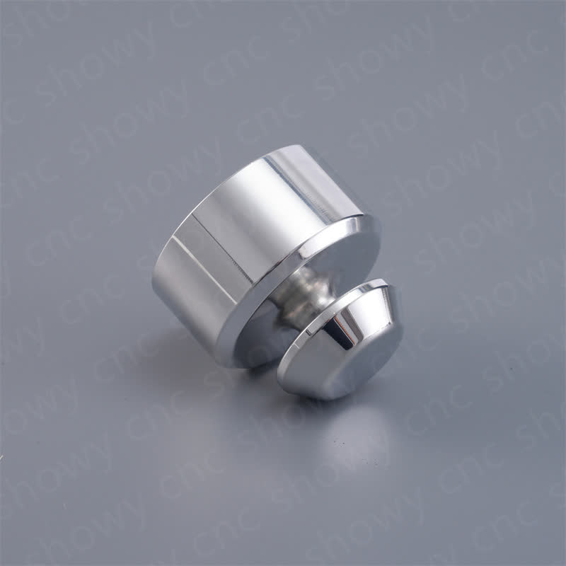


Driven by collaborative robots and high-end consumer electronics, demand for micro-precision machining of dexterous hand parts is rapidly rising. These parts usually involve multi-finger joints, micro-drive shafts, fingertip sensor brackets and flexible connectors, which impose stringent requirements on CNC parts custom machining in terms of size stability, surface finish and batch consistency. As a manufacturer of deep precision CNC parts custom machining, we systematically disassemble the core process of dexterous hand structural parts-the applicable boundaries of 3-axis, 4-axis and 5-axis milling, the cutting strategies of different materials under micro features, and the effects of surface treatments such as anodizing, sandblasting and polishing on Ra value and appearance consistency, helping procurement engineers and technical teams identify risk points in advance at the DFM stage.
Typical Structure and Machining Difficulties of Dexterous Hand Parts
A dexterous mechanical hand with 12 - 20 degrees of freedom is described. Its core moving parts include: finger root hinge shaft (diameter usually 2 - 5 mm), knuckle link (length 8 - 2 ~ 5 mm, wall thickness 0.3 - 0.8 mm), fingertip tactile array support (multidirectional microporous array, aperture 0.5 - 1.5 mm) and palm driving cam or synchronous pulley. The common characteristics of these parts areSmall feature size, tight tolerances, low surface roughness, moderate batch requirements (500~50,000 pieces)。
The main processing difficulties are concentrated in three aspects:
- microfeature clamping deformationFor connecting rod parts with wall thickness less than 0.5 mm, local stress deformation is easy to occur in conventional clamping, and springback after machining leads to size over-tolerance.
- Coaxiality Control in Polyhedral AttitudeKnuckle links need at least three surfaces parallel to each other and the thickness is consistent, the positioning error of single-axis 3 machine tools will accumulate;4-axis or 5-axis linkage milling can complete multiple non-parallel surfaces in one clamping, and the accumulated error will be controlled within ±0.01 mm.
- Surface finish and appearance consistency: Dexterous hand for end users, fingertips and palm parts require high gloss (Ra ≤ 0.4 μm) and no visible scratches, which puts higher standards on tool path planning, cutting parameters and subsequent polishing/plating processes.
Material selection: from structural strength to surface technology
The material selection of dexterous hand parts depends not only on strength and weight, but also on the compatibility of subsequent surface treatment and batch cost. The following are several materials commonly used in engineering practice and their characteristics:
| materials | Typical brand | Tensile strength (MPa) | Density (g/cm³) | Recommended surface treatments | applicable scenarios |
|---|---|---|---|---|---|
| aluminium alloy | 6061-T6 / 7075-T6 | 310 / 570 | 2.7 / 2.8 | Anodizing + sandblasting | knuckle link, palm brace (weight loss priority) |
| stainless steel | SUS303 / 17-4PH | 520 / 1300 | 7.9 | Electropolishing/Dacromet | Articulated shaft, cam (wear resistance and fatigue life are preferred) |
| titanium alloy | Ti-6Al-4V | 880 | 4.4 | Chemical polishing/anodizing | High-frequency impact-loaded joints (aerospace dexterous hand) |
| engineering plastics | PEEK / PEI | 100 / 95 | 1.3 / 1.25 | Natural color injection molding/painting | Finger pad, low load transmission (insulation and noise reduction requirements) |
Note when selecting: aluminum alloy is light and easy to cut, but the thickness of anodic oxide film is usually 5~25 μm, which will slightly change the shape size (outward expansion). This allowance shall be reserved for drawing design;17-4PH stainless steel has high strength but large cutting force. It is recommended to adopt small diameter fine turning + sufficient coolant strategy, and the tool life is about 60% of 303 stainless steel.
Process Boundary and Selection Logic of 3-axis, 4-axis and 5-axis Milling
Most of the features of dexterous hand parts can be completed by 3-axis machining center, but complex hinge structure and special-shaped connecting rod often need 4-axis or 5-axis linkage.Part geometric complexity, coaxiality/parallelism requirements, and unit cycle cost。
3-axis milling: cost first, suitable for regular geometry
Suitable for flat finger support, simple L-link. Key control points include:
- Tool diameter and wall thickness matching: When processing 0.5 mm wall thickness, it is recommended to use 0.3~0.4 mm end mill, speed 12,000~15,000 rpm, cutting depth ap ≤ 0.15 mm/layer, avoid vibration marks.
- Clamping method: vacuum adsorption or soft claw is preferred after fine turning chuck to reduce clamping marks and deformation.
- Turn-over positioning: every time the tool is turned over and reset, the accumulated positioning error is about ±0.02~0.05 mm. If the parallelism required by the drawing is ≤ 0.01 mm, the 3-axis scheme is not applicable.
4-axis milling: cylindrical and end surfaces in one setup
Suitable for rotating body features such as articulated shafts with steps and timing pulleys. A axis (or B axis) rotation and X/Y/Z three-axis linkage can machine multiple axially distributed features in one clamping, and the coaxiality can be controlled within 0.01 mm. Note: Collision simulation in CAM software must be used for interference inspection between tools and workpieces when 4 axes are linked, especially tools with short diameter and large aspect ratio.
5-axis linkage: complex free surface and deep cavity features
When the dexterous hand joint contains a non-planar transition surface (such as the integrated shell of the multi-finger root of the palm), 5-axis simultaneous milling can keep the angle between the tool axis and the surface normal at 15°~25° and avoid cutting at the tip point. The machining time of this kind of parts is usually 1.5~2.5 times that of 3-axis, but it eliminates multiple clamping and positioning errors, and the comprehensive CTQ (key quality characteristics) achievement rate is significantly improved.
Surface finish control: Process path from Ra 0.8 μm to Ra 0.4 μm
Smart finger tips and exposed structural parts often require Ra ≤ 0.4 μm, and some mirror display parts require Ra ≤ 0.2 μm. CNC milling alone is difficult to achieve directly, and multiple post-processing procedures are required:
- Optimization of finish milling parametersAluminum alloy finish milling selects round nose cutter (R0.2), F value 80~120 mm/min, ap 0.05~0.1 mm, feed direction along the forward milling, can stably reach Ra 0.6~0.8 μm.
- Vibration polishing/abrasive flowFor inner cavity and curved surface, Ra can be reduced to 0.4~0.6 μm by vibration polishing for 30~60 min, and burrs can be removed simultaneously.
- Electropolishing (stainless steel/titanium)Current density 25~35 A/dm², temperature 55~65°C, treatment 8~12 min, surface Ra up to 0.2~0.4 μm, and no risk of hydrogen embrittlement.
- Chemical polishing + anodizing (aluminum): If color appearance is required, the film surface Ra after anodization is basically consistent with the substrate. It is recommended that the substrate Ra before oxidation is ≤ 0.4 μm, otherwise the oxide film will amplify microscopic ripples.
Batch consistency control points: sample the roughness (contact roughness meter, ISO 4287 standard) before and after the polishing process, and record the Ra range within the batch; when the range exceeds 0.15 μm, trace the tool wear or polishing medium concentration.
Common Failure Modes and Avoidance Strategies
- Microhole array chip plugging: Fingertip sensor hole diameter ≤ 0.8 mm is easy to cause poor hole diameter due to chip accumulation. Countermeasures: Use internal cooling micro drill (diameter 0.6~1.0 mm), exit chip removal every 3~5 holes drilled, coolant pressure ≥ 0.8 MPa.
- Warpage of thin-walled parts after machining: 6061 aluminum thin wall parts (≤0.5 mm) warpage can reach 0.03~0.05 mm within 24 h after finishing milling. Countermeasures: adopt "rough milling to leave 0.1 mm → stress release 2 h → finish milling" two-stage process, finish the subsequent surface treatment within 4 h after finishing milling.
- uneven anodized color film: Too high hanging density of batch parts leads to shielding effect, local film color is dark. Countermeasures: hanging tool spacing ≥ 2 times the maximum thickness of the workpiece, oxidation tank stirring speed 0.5~1.0 m/s.
- Insufficient coating adhesion: Stainless steel parts before electroplating pickling is not thorough, residual oil caused by nickel layer foaming. Countermeasures: alkaline degreasing 40~50°C × 10 min + dilute sulfuric acid activation 30 s, drying within 2 hours to complete electroplating.
DFM suggestions and key points for review of incoming drawings
Upon receipt of a Dexterous Hand part drawing, our engineering team issues a DFM report from the following dimensions to help customers optimize manufacturability prior to design freezing:
- Minimum feature size check: Confirm whether the minimum drilling hole, groove width and rib thickness are within the range of tool capacity (if the minimum drilling hole is 0.2 mm, it needs to be dedicated to micro-drilling, and the cost increases by about 40%~60%).
- rationality of tolerance classification: Non-mating surface is recommended to be relaxed to ±0.05 mm, and only ±0.01 mm tolerance is reserved for mating clearance surface and sensor smooth surface, which can significantly reduce processing time and cost.
- Surface treatment compatibilityIf the parts have both high brightness requirements and anodized color film, it is necessary to clarify the boundary of partition treatment to avoid color difference of oxide film in bright area.
- clamping and positioning datum: Reserve 2~3 positioning holes or flat surfaces (Ra ≤ 1.6 μm) for quick clamping in subsequent processes.
FAQ: Dexterous hand parts precision machining high-frequency problems
Can the batch tolerance of aluminum alloy parts with wall thickness of 0.4 mm of smart finger joint link be ±0.01 mm?
Yes, but it is necessary to adopt 4-axis or 5-axis one-time clamping machining, fine milling allowance of 0.05 mm, and complete subsequent processes within 4 hours after fine milling to reduce stress rebound. Batch consistency depends on the first piece confirmation and three-dimensional sampling every 50 pieces (refer to AQL 1.0 for sampling scheme).
Fingertip parts require anodizing + polishing double-sided process, how to evaluate the delivery date?
Polishing and anodizing are irreversible. If polishing is performed first and then oxidized, the film surface will be covered with polishing lines, resulting in a decrease in gloss. The correct sequence is oxidation first and then polishing (electrolytic polishing or mechanical polishing). The total increase of the two processes is 3~5 days. The batch can be digested within the total delivery period of 15~25 days.
17-4PH stainless steel hinge shaft and PEEK transmission parts, how should the surface roughness match?
Ra ≤ 0.4 μm is recommended for shaft surface (dynamic friction pair) to reduce starting torque and wear; Ra 0.8~1.6 μm is recommended for inner hole mating surface of PEEK parts, which is too smooth to reduce fitting force. H7/f7 or H8/e8 is recommended for fitting clearance tolerance, which is adjusted according to dynamic load and life requirements.
What is the difference between the unit price and delivery date for a small batch of 200 units and a large batch of 50,000 units?
The cost of CAM program debugging and tool preparation is mainly for small batches, and the unit price is usually 2.5~4 times that of large batches. The unit price decreases after dilution of large batches, but the delivery period may be extended by 5~7 days compared with small batches. We support rapid delivery of small batches starting from 500 pieces, and mass production within 15~25 days.
How to verify batch consistency of dexterous hand parts?
100% full size test for key characteristics (CTQ) before shipment, non-CTQ sampling inspection according to AQL 2.5; surface appearance (scratches, pits, color difference) according to 100% visual inspection + batch range ≤ 0.15 μm roughness monitoring records. All test data are provided with the goods, including three-coordinate report and appearance photos for archiving.
Conclusions and recommendations for action
The essence of dexterous hand parts machining isFind a process window between miniature features, tight tolerances and high appearance requirementsIf you are developing collaborative robots or high-end interactive devices, please send us your Smart Hand part drawings (STEP/PDF). We will issue DFM comments and batch quotations within 1 business day, and arrange quick proofs to verify key size and appearance.