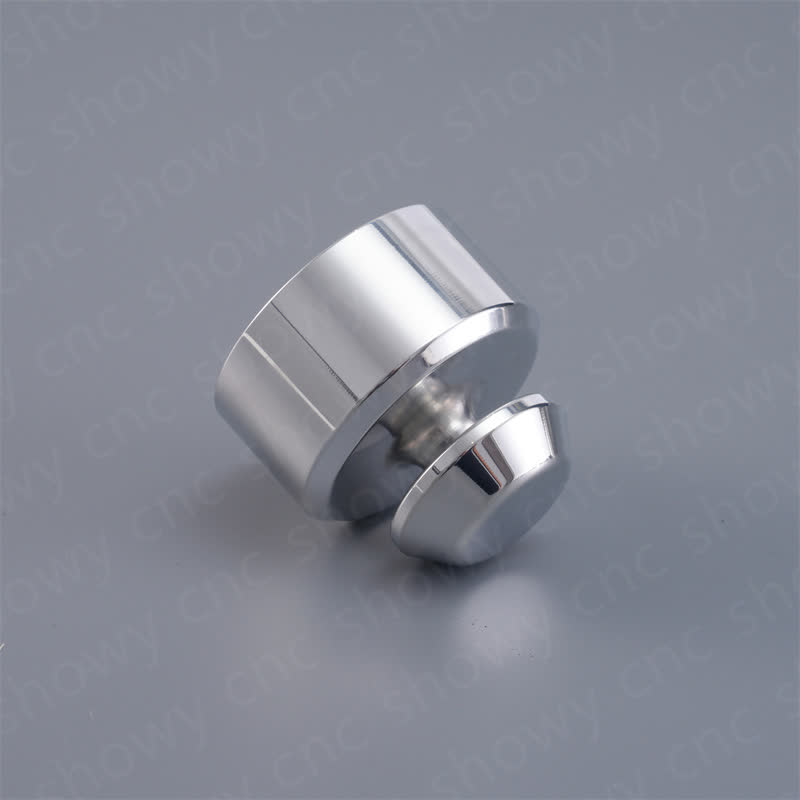


CNC machining of vision camera mounts focuses on balancing high rigidity, lightweight and precise positioning, which directly determines the imaging stability and long-term repeatability of machine vision systems. For mounts made of aluminum alloy, the key challenges are to control thermal deformation, suppress micro-chatter, and ensure flatness and smoothness of optical mounting surfaces. This paper analyzes the key control points of vision camera holder in CNC process, from material selection, tool strategy to final acceptance criteria, providing technical reference for engineers and purchasers.
Material Selection and Rigid Foundation of Vision Camera Stand
Aluminum alloy is the mainstream choice of vision camera mount, its specific strength (strength/density) is much better than steel solution, can effectively reduce the weight of the equipment and improve the dynamic response. In the choice of grades, 6061-T6 and 7075-T6 are the two most common types. 6061-T6 has good cutting performance, isotropic, suitable for most general scenarios; 7075-T6 has a higher yield strength and provides higher structural rigidity at the same weight, but it has a stronger tendency to work harden and has more stringent requirements for tool life and cooling. In addition, marine grade aluminum alloys such as AlMg4.5Mn are often used for outdoor or wet environment vision system brackets due to their excellent corrosion resistance.
CNC routing comparison: applicable boundaries for milling vs. turning
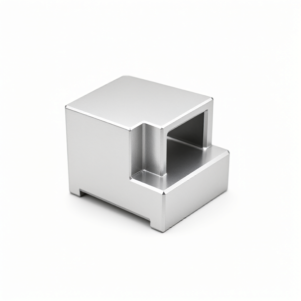
Vision camera supports are mostly complex polyhedra or box structures with flanges. The selection of process routes directly affects rigidity and size chain errors. The following two mainstream schemes are compared to help judge the optimal path under different geometric characteristics.
| process type | Typical applicable structure | rigid dominance | mainly limited |
|---|---|---|---|
| 5 axis machining center milling | Multi-plane, angled or curved light guide bracket | All features are completed in one clamping, the datum is unified, and the accumulated error is minimum. | High requirements for fixture design and five-axis motion envelope, high cost for small batches |
| lathe-milling combined machining | Axle/barrel support with center hole or threaded hole | Turning ensures roundness of revolution, milling end and radial features | Not applicable to complex box structures of non-rotating bodies |
For most vision camera mounts, 3-axis or 4-axis milling is sufficient if the structure is mainly flat and straight; if inclined mounting surfaces or avoidance areas are involved, 5-axis linkage needs to be enabled to avoid positioning drift caused by staged clamping. Turning and milling compound is mainly suitable for special designs where the mount body is cylindrical or cylindrical, such as circular shield mounts for some line scan cameras.
Critical Tolerance Control: From Positioning Datum to Thermal Deformation Compensation
The core function of the vision bracket is to ensure that the camera is stable relative to the optical axis of the workpiece or light source, so the tolerance of the positioning reference surface is directly imaged. Generally, the flatness of the key mounting surface is ≤0.02mm, the hole position is ≤±0.01mm, and the surface roughness Ra is ≤0.4μm. To achieve these indicators, three links need to be controlled: First, rough machining reserves finishing allowance.(0.3-0.5mm) to eliminate stress; secondly, natural aging or artificial aging before finishing (6061-T6 needs ≥10 hours) to stabilize the organization; finally, the finishing process is carried out in the constant temperature workshop (20±2°C), and the process of "semi-finishing → static → finishing" is adopted to offset the residual thermal stress deformation.
Synergistic Effect of Surface Treatment on Optical Properties
Aluminum alloy stents are not directly involved in imaging, but improper surface treatment may introduce reflected stray light or corrosion risk. Anodic oxidation is the most commonly used treatment for aluminum alloy stents. The oxide film formed not only improves wear resistance, but also effectively reduces specular reflection of metal color to surrounding light sources. For scenes with optical stray light control requirements, it is recommended to use matte black or dark gray oxide film with a thickness of 8-12μm to avoid stress cracking caused by excessive thickness. Sandblasting and wire drawing process is mainly used for appearance parts, if the bracket and the camera body direct contact with the optical mounting surface, it is strictly prohibited to carry out any decorative surface treatment, must retain the finished light surface or only passivation treatment, in order to prevent roughness changes introduced shape error.
Batch Consistency Control and Inspection Methods
size drift of the visual support is a major source of hidden costs in mass production. To ensure consistency, SPC control charts should be established to identify key features (such as diameter of optical axis hole, thickness of mounting surface) for Cpk≥1.33 process capability monitoring. Inspection means, CMM for full size sampling, optical projector for profile comparison, roughness meter is dedicated to monitoring the Ra value of optical mounting surface. In addition, incoming inspection should focus on checking the solid solution aging mark of aluminum rod to avoid late deformation caused by the use of incomplete aging materials. For large-volume orders, it is suggested that after the first piece is confirmed qualified, a full size review should be carried out every 50 pieces to balance efficiency and risk.
Frequently Asked Questions (FAQ)
What is the minimum wall thickness of CNC machining of vision camera bracket?
It is usually recommended that the minimum wall thickness ≥1.5mm to ensure structural rigidity and prevent tool vibration during milling. If the design limit is to be as thin as 0.8mm, high speed small tools and optimized paths are required, but the yield will be significantly reduced.
7075 aluminum alloy processing vision bracket how to avoid knife marks?
7075 cutting hardening obvious, easy to leave tool marks. Need to use sharp coated tool, reduce the feed rate to 6-8mm/r, and increase the number of finishing tool. At the same time, ensure that the spindle dynamic balance is good, avoid high frequency chatter.
Does the optical mounting surface roughness of the vision bracket have to be Ra0.4?
Not relatively, but Ra≤0.8μm is recommended. Ra0.4μm is suitable for high magnification or long focal length cameras to reduce reflected glare; Ra0.8μm is sufficient for ordinary industrial cameras.
Is the 5-axis machining vision support necessarily more refined than the 3-axis?
Not necessarily. The advantage of 5-axis is that it can complete multi-faceted features in one clamping and reduce reference conversion errors. If the bracket structure is simple, the accuracy of 3-axis clamping with precision fixtures can also reach the standard, but the cost and efficiency are lower.
How to judge whether the consistency of mass production of visual stent is qualified?
By calculating the process capability index Cpk of critical size, it is required to be ≥1.33. At the same time, combining CMM sampling data and appearance inspection records, it is ensured that both size and surface quality are under control.
Conclusions and recommendations for action
High rigidity CNC machining of vision camera holder is essentially systematic control of materials, processes, environment and inspection. Choosing 6061-T6 or 7075-T6 requires a balance between rigid budget and machining difficulty;5-axis or turn-milling compound routes should match structural geometry; critical tolerances depend on thermal management and finishing strategies; batch consistency requires SPC and multi-level inspection. If you have the design drawings of the vision bracket, you can send them to us. We will provide DFM optimization suggestions, material selection references and batch delivery solutions based on structural characteristics to help you control costs and cycle times while ensuring optical accuracy.