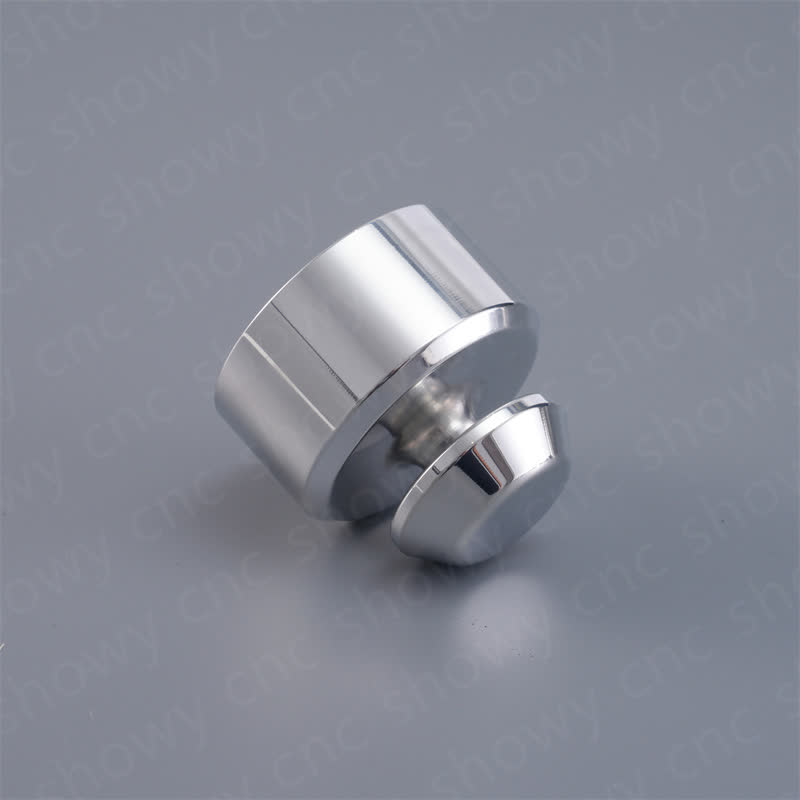


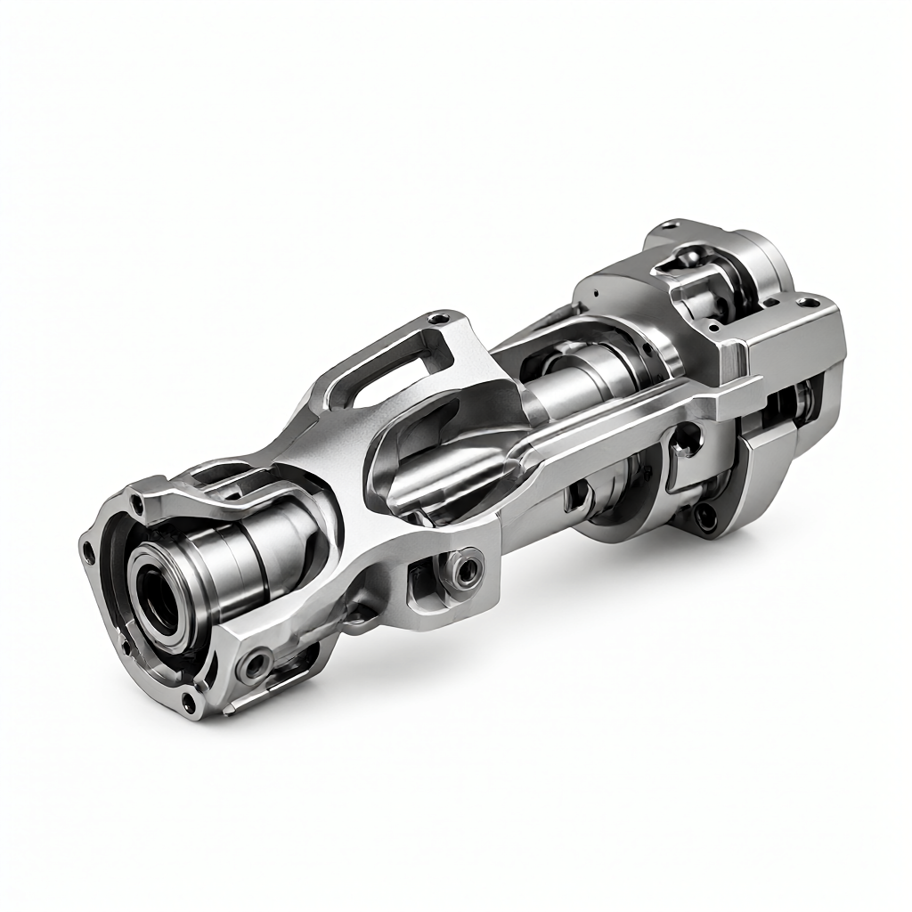
In the lightweight design of automotive parts, material selection directly determines vehicle energy consumption, NVH performance and manufacturing costs. This article makes an in-depth comparison of the performance differences, tolerance control difficulties and surface treatment solutions of aluminum alloys, magnesium alloys, high-strength steels and engineering plastics in CNC machining, helping engineers and purchasers establish a workable selection decision model, and clarifying the impact of different process paths on the appearance consistency and batch stability of the final parts.
Comparison of core indicators of automotive lightweight materials
Lightweighting is not simply about minimizing density. It is about balancing strength, stiffness, cost and workability. The following table lists the key physical parameters and processing characteristics of four commonly used materials in gauge grade applications. These parameters are the basis for developing DFM solutions.
| material type | Density (g/cm³) | Tensile strength (MPa) | CNC cutting toughness | typical application scenarios |
|---|---|---|---|---|
| 6061-T6 aluminum alloy | 2.70 | 290 | High, easy to stick knife | Non-load bearing brackets, radiators |
| AZ91 magnesium alloy | 1.81 | 180-300 | Medium, explosive | Interior trim, hub liner |
| 42CrMo4 steel | 7.85 | 700-1000 | Low, chip breaking required | Bearing, shaft core parts |
| PA66+GF30 plastic | 1.35 | 180 | High, need cooling. | Snap, sensor housing |
Engineering interpretation:Aluminum alloy is the first choice for structural parts due to its good electrical conductivity and moderate hardness; magnesium alloy has significant weight reduction effect but hydrogen embrittlement risk needs attention; steel is heavy but has long fatigue life, suitable for high stress joints; engineering plastics are suitable for non-load-bearing functional parts, and heat deformation temperature HDT needs attention.
Analysis of CNC machining process difficulties of different materials
Sticky knife and gloss control of aluminum alloy
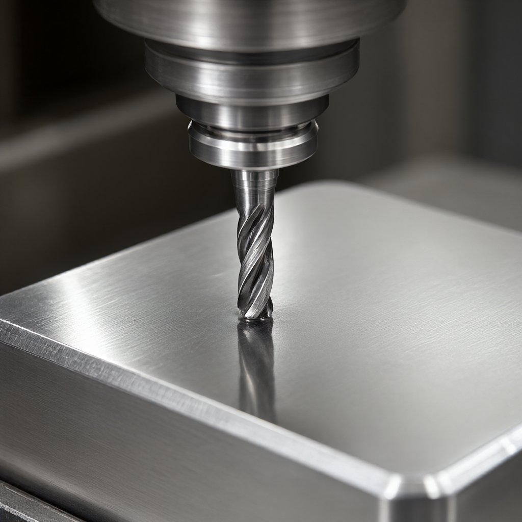
Chip build-up is easy to occur when cutting aluminum, resulting in "pockmarks" or uneven brightness on the surface. The key to solving this problem is to use fluorine-containing cutting fluid and strictly control the amount of back cutting. For high-gloss surface requirements, it is necessary to use a small-diameter precision milling cutter with a speed controlled at 8000-12000 rpm and a feed of 0.1-0.2 mm/rev. We provide high-gloss surface/mirror effect treatment, and eliminate tool marks by optimizing the cutting path to ensure consistent batch appearance.
Safety and Corrosion Protection of Magnesium Alloys
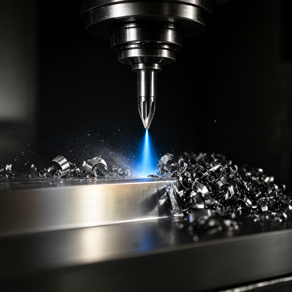
Magnesium alloy dust may burn in the air, CNC machining must be equipped with wet cutting system or special flame retardant coolant. In addition, magnesium oxide film thin, CNC immediately after the need for sealing anodization or Dacromet treatment to prevent corrosion. If the design allows, it is recommended to increase the corrosion allowance of 0.05mm, and in the drawings marked prohibited areas.
Hot Deformation and Chip Breaking of Steel
High-strength steel cutting produces high heat, if the heat dissipation is not appropriate, the thermal expansion and contraction of the parts will lead to size deviation. 5-axis machining center can reduce the peak cutting force by continuously rotating the spindle. It is recommended to use indexable inserts with a cutting edge radius of 0.4-0.8mm, which are directly rushed into the cutting area with high-pressure cooling. Tolerance control needs to consider 0.5- 1mm thermal compensation, especially in long-axis parts.
Engineering assurance of surface appearance and batch consistency
Our core strength lies in integrating appearance quality into process control: 72 CNC machines cover 3/4/5 axis milling, walking and turning and milling compound, supporting aluminum, steel, engineering plastics and other materials. Through first part verification and process inspection, we ensure high finish, no scratches and no defects. Mass production 15-25 days delivery, size accuracy up to ±0.01mm, surface finish Ra0.4μm.
- Anodic oxidation:Suitable for aluminum alloy, film thickness 10-40μm, color can be customized, high hardness, wear resistance.
- Sand blasting and wire drawing:Suitable for appearance parts, providing matte or texture effect, strict control of sand particle size 120-240 mesh.
- Plating:Suitable for steel/copper, thickness 5-10μm, pay attention to hydrogen embrittlement risk, after treatment to remove hydrogen.
DFM recommendations and tolerance settings at design stage
Lightweight design needs to avoid process defects at the drawing stage. For aluminum alloy thin-walled parts (wall thickness)<1.0mm),建议加强筋布局对称,避免铣削变形;对于深腔件(深宽比>6:1), reserve 0.1mm tool withdrawal space to prevent tool vibration caused by excessive overhanging. Tolerance setting, non-mating surface recommended ±0.05mm, key mating surface ±0.01mm. If it involves injection molding parts and CNC parts assembly, it is necessary to reserve 0.2-0.5mm thermal expansion gap, especially in high temperature engine hood inner parts.
Please refer to our surface treatment process instructions for the effect of different coatings on size. For example, plating increases the diameter by 0.02-0.05mm, which should be deducted from the blank size during design, otherwise interference will occur during assembly.
Quality inspection system and failure mode avoidance
To ensure the reliability of parts, we carry out full-link inspection: incoming inspection to confirm material grade, first article to confirm process parameters, process inspection to monitor size drift, shipment inspection to cover 100% of critical size. Equipped with three-coordinate, optical measurement, roughness meter and other detection means. Common failure modes include: corrosion caused by oxide film damage of aluminum parts, distortion caused by residual stress release of steel parts, hydrogen embrittlement fracture of magnesium parts. Avoidance options include: After assembly, secondary anode sealing, aging treatment to remove stress, control plating current density.
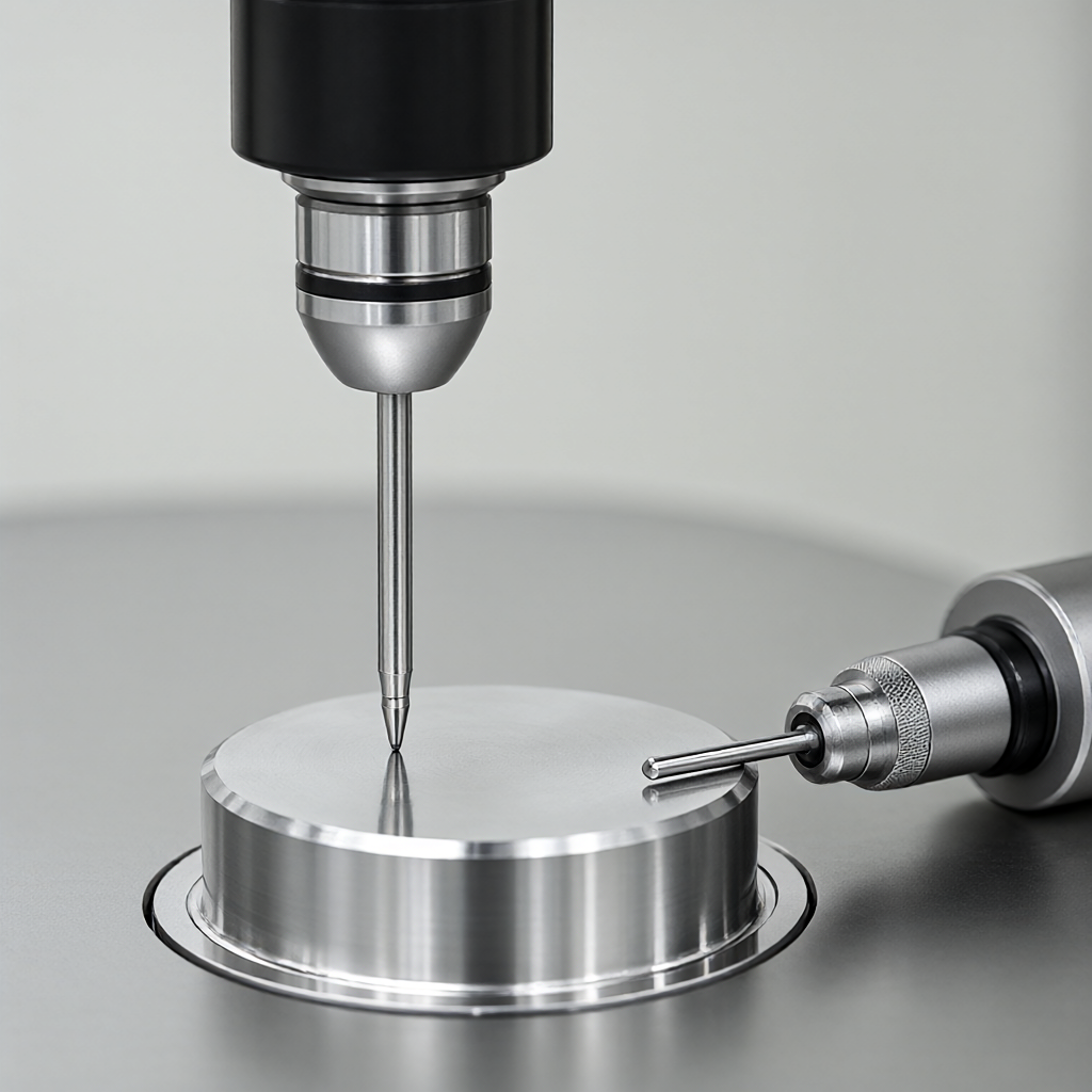
For medical or aerospace automotive parts, material certificates and nondestructive testing reports (e.g. X-Ray or penetrant testing) are required to prove that there are no internal cracks. The relationship between measured values and tolerance zones is clearly indicated in the inspection report for quick traceability by customers.
High frequency technical FAQ
How to anodize aluminum alloy after CNC machining in order not to burn?
The key lies in controlling the impurity content in aluminum, selecting high-purity aluminum ingots (such as 6061 brand) and avoiding oil pollution; maintaining the temperature of anodizing bath at 20-25°C, voltage 12-18V, and film thickness uniformity through current distribution simulation optimization.
How to control the batch color difference of magnesium alloy parts?
The color difference is due to the different thickness of the oxide film. It is recommended to complete the same batch of oxidation treatment within the same shift, strictly monitor the bath concentration and temperature fluctuation not to exceed ±2°C, and use standard color chart comparison.
Engineering plastic PA66 injection molding or CNC turning which cost is lower?
High volume (>1000 pieces) injection molding costs are lower due to lower mold amortization; small volume (<100 件)CNC 车削更经济,无模具费且交期短(15-25 天内可量产交付)。
42CrMo4 steel after quenching and tempering treatment uneven hardness how to do?
It is suggested to optimize the uniformity of heat treatment furnace temperature, adopt vacuum quenching or rapid oil cooling, and charge in the same furnace to ensure batch consistency.
What is the minimum tolerance for machining slender shafts with a centering machine?
The double spindle structure of the centering machine has high rigidity, the minimum tolerance can reach ±0.005mm, and the Ra value can reach Ra0.4μm. It is suitable for high-precision small parts such as automobile harness brackets.
Conclusions and guidelines for action
Lightweight design of automotive parts is systems engineering. Material selection requires a combination of strength, weight, cost and appearance requirements. Aluminum alloys provide a good balance in most structural parts, magnesium alloys have weight reduction advantages in interior parts, steel is suitable for high stress areas, and plastics are suitable for functional parts. The key lies in avoiding processing defects through DFM and relying on rigorous process inspection to ensure batch consistency.
If you have drawings or samples of specific automotive parts, please send them to our engineering team. We offer quotations within 24 hours and propose optimization suggestions free of charge at the DFM stage to ensure that your lightweight solution is reliable and cost-effective.