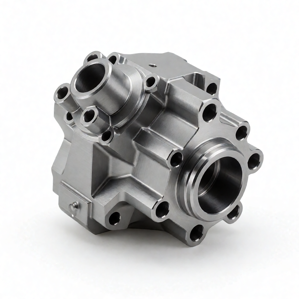
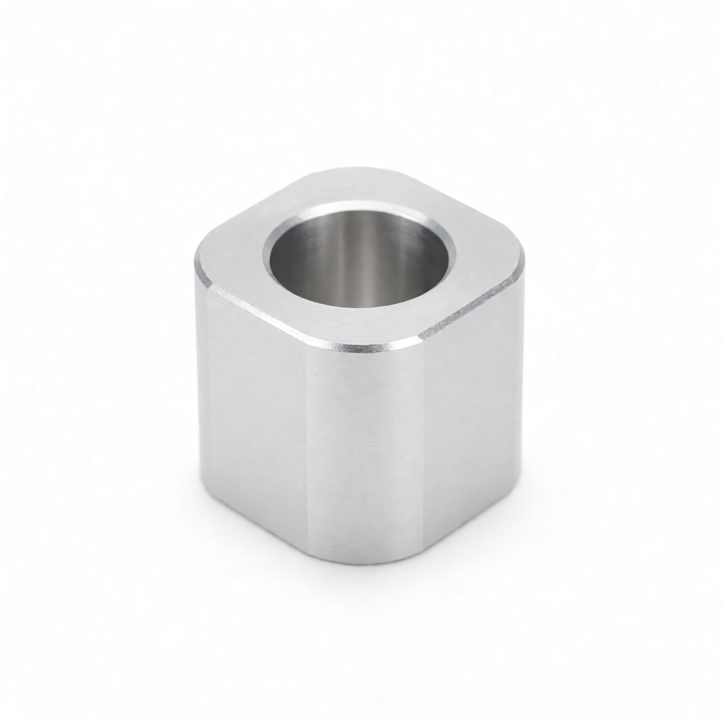
Aluminum surface finish quality is often defined by roughness average (Ra) values, yet many engineers and procurement specialists misinterpret how Ra correlates with visible aesthetics, functional performance, and machining feasibility. This guide explains Ra parameters from a manufacturing perspective, connecting specific numerical ranges to process capabilities (CNC milling, turning, lapping), material behavior, and inspection methods. Understanding these metrics helps avoid specification ambiguity, reduces rework, and ensures parts meet both visual and dimensional tolerances before production launch.
Understanding Ra Values in Aluminum CNC Machining
Surface roughness Ra is the arithmetic mean of the absolute profile height deviations over a specified sampling length. In CNC aluminum machining, Ra is not an inherent material property but a result of tool geometry, cutting speed, feed rate, and post-processing.
For aluminum alloys like 6061-T6 or 7075-T651, low Ra values indicate high polish or grinding, while higher values suggest standard milling or turning. A critical nuance for buyers is that "smooth" in marketing often means Ra ≤ 0.8 µm, which requires specific post-CNC operations beyond standard milling.
- Standard CNC Milling: Typically achieves Ra 1.6 µm to 3.2 µm without post-treatment.
- CNC Turning (Lathe): Can achieve Ra 0.8 µm to 1.6 µm with sharp tool geometry.
- Post-Processing (Polish/Blast): Required to reach Ra < 0.4 µm for mirror-like finishes.
Typical Ra Ranges and Corresponding Surface Textures
The following table maps common Ra values to their visual appearance and typical manufacturing methods. This reference helps align design expectations with production capabilities.
| Finish Type | Typical Ra Value (µm) | Visual/Feel Description | Common Process |
|---|---|---|---|
| Coarse | 6.3 – 12.5 | Visible tool marks; rough to touch | Rough milling, casting |
| Standard | 1.6 – 3.2 | Smooth to touch; minor texture visible | Finished CNC milling/turning |
| Fine | 0.4 – 0.8 | Glassy appearance; low light reflection distortion | Centerless grinding, fine polishing |
| Mirror | < 0.1 | Reflective; high-grade cosmetic | Multi-stage lapping/polishing |
Important Note: Achieving Ra 0.4 µm on large aluminum surfaces is significantly more expensive and time-consuming than Ra 1.6 µm due to the need for precision lapping or abrasive belt polishing. Specify Ra only where functionally or cosmetically critical to control costs.
Impact of Ra on Aluminum Anodizing Quality
Surface finish directly affects anodizing uniformity and color consistency. Rough surfaces (Ra > 3.2 µm) trap etchant and can cause pitting, uneven oxide layer thickness, or dark spots in anodized parts. This is a common failure mode in consumer electronics and automotive trim components.
To ensure high-quality anodizing, engineers should specify a maximum Ra of 1.6 µm on anodized surfaces, ideally 0.8 µm for Class I cosmetic anodizing. Pre-anodizing machining must minimize cross-hatching and tool marks, which are amplified during the etching process.
Practical Considerations for Specifying Aluminum Surface Finish
Machining Parameters That Influence Ra
While post-processing sets the final Ra, initial CNC parameters establish the baseline. Key factors include:
- Tool Diameter & Insert Geometry: Smaller tool radii generally produce lower Ra on curved surfaces.
- Feed Rate: Increasing feed rate increases Ra linearly. For aluminum, low-to-moderate feed rates help achieve Ra 1.6 µm.
- Spindle Speed: Aluminum requires high surface speeds. Optimal RPM prevents built-up edge (BUE), which dramatically increases Ra.
- Coolant/Lubrication: Inadequate coolant leads to thermal buildup and increased surface waviness.
Inspection and Measurement Methods
Do not rely on visual inspection or "feel" for Ra compliance. Use contact profilometers (Stylus) for standard surfaces (Ra 0.2 – 6.3 µm). For very smooth surfaces (Ra < 0.1 µm) or optically critical parts, use optical interferometry or white-light confocal microscopy, as stylus probes can damage or distort the surface under measurement.
Specify the sampling length (typically 1mm for general engineering) and cut-off filter (e.g., 0.8mm) in the drawing to avoid interpretation differences between inspectors.
Common Failure Modes and How to Avoid Them
Even with correct Ra values, surface quality can fail if machining or handling introduces defects. Common issues include:
- Cross-Hatching: Caused by overlapping pass directions in 5-axis milling. Solution: Align final finishing pass direction with primary aesthetic view.
- Tool Burn (Gouges): Sudden changes in tool path or worn inserts. Solution: Implement in-process tool wear monitoring and sharp tool insertion.
- Waviness/Macro-Roughness: Vibration or chatter during machining. Solution: Reduce depth of cut, increase spindle rigidity, or use high-rev finishing strategies.
- Handling Scratches: Aluminum is soft; post-machining scratches degrade surface finish. Solution: Use plastic jigs, vacuum lifting, and protective films during inspection and packaging.
Specify "scratch-free" or "cosmetic grade" in addition to Ra values to enforce handling standards beyond just surface texture.
Cost and Lead Time Implications of Surface Finish Tolerances
There is a direct correlation between stricter Ra requirements and unit cost. A standard milled aluminum part at Ra 3.2 µm is the baseline. Tightening to Ra 1.6 µm may require a second machining pass or specific tooling, increasing cycle time by 15-20%. Moving to Ra 0.8 µm typically mandates post-CNC polishing or grinding, adding 2-5 days to lead time and increasing cost by 30-50% depending on surface area complexity.
For batch production, maintaining consistent Ra across hundreds of units requires stable CNC setups, tool life management, and first-article inspection protocols. Manufacturers with dedicated quality control (CMM, profilometer) and DFM support can offer better batch consistency.
Frequently Asked Questions About Aluminum Surface Finish
What is the standard Ra value for CNC machined aluminum parts?
Standard CNC milling typically achieves Ra 1.6 µm to 3.2 µm. If no Ra is specified, expect this range. For cosmetic or sealing surfaces, explicitly request Ra 0.8 µm or lower.
Can anodizing smooth out rough surfaces?
No. Anodizing does not remove material; it grows an oxide layer on top of the surface. Roughness (Ra) is preserved and can become more visible. Surface must be machined or polished to desired Ra before anodizing.
How do I measure Ra on large flat aluminum plates?
Use a stylus profilometer with a 1mm sampling length for Ra 0.2–6.3 µm. For large areas, specify multiple measurement points per surface to ensure uniformity, as machining can vary across a tool path.
What is the difference between Ra and Rz?
Ra is the arithmetic average roughness; Rz is the maximum peak-to-valley height over 5 sampling lengths. Rz is more sensitive to individual peaks and scratches. If cosmetic scratch-free quality is critical, specify limits on Rz (e.g., Rz < 5 µm) alongside Ra.
Does aluminum alloy type affect achievable Ra?
Yes. Harder alloys like 7075-T651 wear tool inserts faster, which can increase Ra if tool life is not managed. Softer alloys like 5052-O or 6061-O allow for higher feed rates but are more susceptible to smearing, which can increase apparent roughness if cutting parameters are not optimized.
Conclusion and Next Steps
Specifying aluminum surface finish requires balancing functional needs, aesthetic requirements, and cost. For best results, define Ra values based on actual process limits (not just ideal preferences), mandate pre-anodizing Ra limits, and include handling/scratch control requirements. If you need high-gloss, scratch-free aluminum parts with consistent batch quality, review your drawings for specified Ra and Rz limits. Send your CAD files and specifications to request a DFM assessment and quote for precision CNC machining and surface treatment.